Removal and replacement of ADU modules
8-30 Chapter 8: Service & maintenance 99-145912-A
5. Remove the 4x4 mm Allen screws (thread size M5) (visible when the
connectors are removed) and remove the Cross Elevation DDM.
To insert a new DDM follow the instructions above in reverse order.
8..6.4.2 To replace the Elevation DDM
To remove the Elevation DDM, do as follows:
1. Open the service hatch.
2. Switch off the power to the antenna on the service switch.
3. Rotate the antenna pedestal so that the elevation DDM faces the
service hatch.
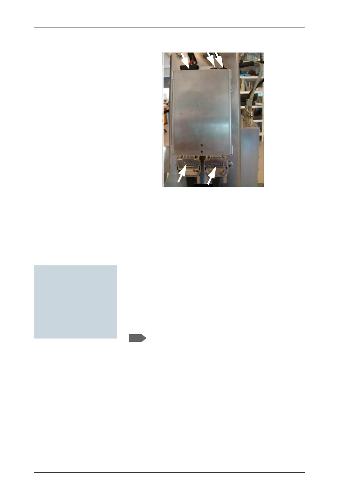
4. Disconnect the 3 connectors at the front of the Elevation DDM,
then the 2 SUB-D connectors at the rear of the Elevation DDM.
Figure 8-28: Replacing the DDM — remove connectors
Tools needed:
• TX20 (SAILOR 900), TX30
(SAILOR 800)
• 4 x 150 mm Allen key
(located inside the service
door of the ADU)
•Flat head screw driver
Note that two connectors are identical. Mark them so you
know where each connector belongs to (e.g. left, right).

 Loading...


