Maintenance and fault finding
Block Up Converter Systems 6700/6900 series User Guide 105
Checking the resistance of an RF waveguide switch
To check the resistance of an RF waveguide switch:
1 Disconnect the control cable from the RF waveguide
switch.
1 Use a multimeter to check the resistance of the coils and
tell-back contacts at the connector on the switch.
Table 25 shows the expected results at RF waveguide
switch position 1 and position 2.
NOTE
To manually change a switch position,
remove the cover on the actuator of the
switch, then rotate the actuator.
NOTE
The pin numbers in Table 25 apply to the
connectors at both ends of the cable
connecting the RF waveguide switch to the
redundancy controller.
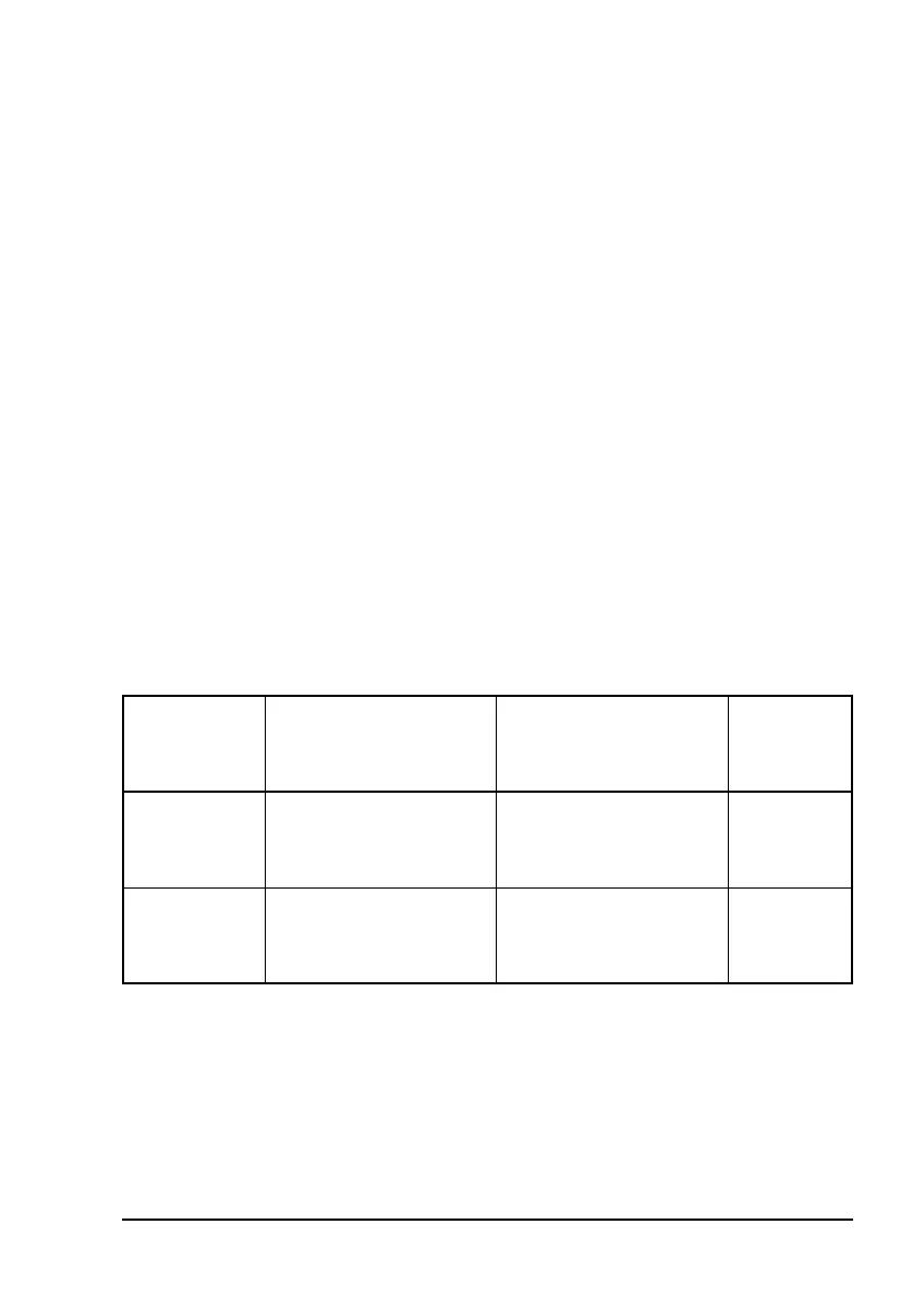
Table 25: Resistance of coils when the RF waveguide
switch is in positions 1 and 2
RF waveguide
switch
Resistance of pin A
(coil 1) to pin B
(common)
Resistance of pin C
(coil 2) to pin B
(common)
Tell-back
contact
Position 1
(coil 1 open
circuit)
Very high 100 Ω (WR137, WR75)
24 Ω (WR229)
D–E closed
F–E open
Position 2
(coil 2 open
circuit)
100 Ω (WR137, WR75)
24 Ω (WR229)
Very high D–E open
F–E closed
NOTE
The resistance of pin C to pin B for position 1 of
the RF waveguide switch is not applicable to
transmit-only systems.