Overview
Block Up Converter Systems 6700/6900 series User Guide 19
Switches
The control panel of the redundancy controller has one switch.
The function of this switch is to select the AC input voltage
(115 or 230 V AC).
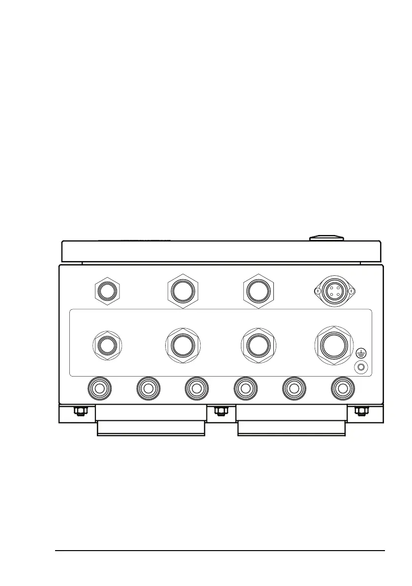
Connectors
The connector panel is located at the bottom of the
redundancy controller.
Figure 10: Connector panel on the redundancy
controller
BUC Switch Control
LNB Switch Control
BUC 2 Serial
BUC 1 Serial BUC 1 Control
BUC 2 Control
AC Power Input
Auxiliary I/O
Rx IF Input 2Rx IF OutputRx IF Input 1Tx IF Output 2Tx IF InputTx IF Output 1