EasyManua.ls Logo

Code Blue CB 2-e - User Manual

Default Icon
63 pages
Print Icon
To Next Page IconTo Next Page
Loading...
800.205.7186
www.codeblue.com
Administrator Guide
CB 2 Series
Installation | Confi guration | Operation | Troubleshooting

Questions and Answers

  • D
    Dennis NielsenAug 10, 2025
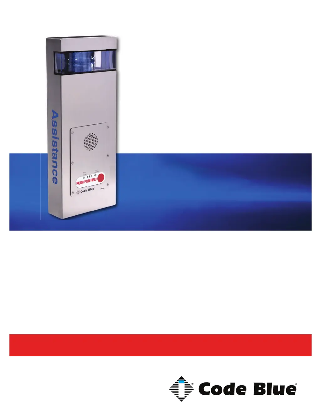
    How to fix volume too low or loud on Code Blue Security System amp?
    • Z
      Zachary SanchezAug 10, 2025
      To address low or loud volume on your Code Blue Security System's amplifier, first adjust the volume within the IA4100/IP5000 programming. For IA4100, use in-call commands 28 to increase and 29 to decrease volume. For IP5000, modify the Public Address Gain under hardware settings. Additionally, manually adjust the input gain on the amplifier using the input gain dial.
  • S
    Sarah CaseyAug 17, 2025
    What to do if there is no power to Code Blue Security System unit?
    • E
      Erica OwensAug 17, 2025
      If your Code Blue Security System unit has no power, check the following: * For CB 1 or 5 units, ensure 120V AC is reaching the transformer. * For CB 2-e units, confirm either Hi-Voltage to the power brick or 24V AC to the unit if it's a low voltage setup. * For WM-180° units, verify 24V AC is supplied to the unit.
  • J
    Jennifer PowersAug 25, 2025
    What to do if strobes are not working on Code Blue Security System?
    • J
      Jonathan PruittAug 26, 2025
      To troubleshoot non-working strobes on your Code Blue Security System, check the 5 amp slow blow inline fuse located between the transformer and the 5-finger manifold. Also, inspect the power connector at the 5-finger manifold and the red/black power wire from the strobe. To test the strobe's functionality, short the yellow relay wires from the strobe. If the strobe flashes, verify the programming in the IA4100/IP5000 speakerphone.
  • G
    Greg FullerSep 1, 2025
    How to troubleshoot PAS not working on Code Blue Security System?
    • J
      jgilbertSep 1, 2025
      If the PAS (Public Address System) is not working on your Code Blue Security System, remove the control cable from the amplifier to keep the amp on at all times, and then try a new test call. Also, test the power from the transformer to the amp.

Summary

Power Requirements Overview

Faceplate Power Requirements

Power consumption details for various faceplate models.

Light Component Power Requirements

Power consumption details for different light components.

High Voltage AC Components

Power specifications for high voltage AC components.

High Voltage Models

Power consumption for high voltage models.

Legacy Power Requirements Details

24 V AC Component Specs

Power specifications for 24V AC components in legacy models.

12 V DC Components Specs

Power specifications for 12V DC components in legacy models.

Software Configuration Options

Blue Alert MNS Software

Mass Notification Software for incident response and multi-layered notifications.

Blue Alert EMS

Software for remotely controlling communication devices and managing events.

ToolVox

Emergency management platform for blue light phone networks.

Replacing LED Light Connectors

Replacing LED Light Connectors

Step-by-step guide to replacing LED light connectors with Wago connectors.

CB 2-a Installation Instructions

CB 2-e Installation Instructions

Basic Installation Instructions

Step-by-step guide for installing the CB 2-e unit.

Legacy CB 2-e Installation Instructions

Legacy CB 2-e with Public Address Installation Instructions

ELECTRICAL WIRING

Instructions for connecting electrical power sources.

COMMUNICATIONS WIRING

Instructions for connecting communication lines.

Legacy CB 2-e with AED Housing Installation Instructions

WIRING

Detailed instructions for connecting power wires.

CB 2-s Installation Instructions

INSTALLATION PROCEDURES

Step-by-step process for installing the unit.

Pole Mount Bracket Installation

AED Access and Maintenance Guide

AED Access Methods

Four methods to access the Automated External Defibrillator (AED) device.

PROGRAMMING

Instructions for programming the door controller and syncing key fobs.

CB 2 Series Remote Mount Beacon;Strobe Installation

S-1000;S-1050;S-2000 Installation Instructions

OPERATION

Instructions for activating LEDs in steadyburn and flash modes.

PHOTOCELL FEATURE (S-1050 MODEL)

Details on the photocell feature for automatic light control.

Programming Primary & Secondary Modes

Guide to programming flash modes and steadyburn modes for lights.

CB 2-a Standard Wiring Diagram

CB 2-a Standard Wiring Diagram

Wiring diagram for CB 2-a standard configuration.

CB 2-a PoE Wiring Diagram

CB 2-a PoE Wiring Diagram

Wiring diagram for CB 2-a Power over Ethernet (PoE) configuration.

Legacy CB 2-a Wiring Diagram (prior to 2020)

Legacy CB 2-a Wiring Diagram (prior to 2020)

Wiring diagram for legacy CB 2-a models before 2020.

CB 2-e Standard Wiring Diagram

CB 2-e Standard Wiring Diagram

Wiring diagram for CB 2-e standard configuration.

CB 2-e PoE Wiring Diagram

CB 2-e PoE Wiring Diagram

Wiring diagram for CB 2-e Power over Ethernet (PoE) configuration.

CB 2-e 120 V Standard Wiring (2015-2020) with Triad Transformer

CB 2-e 120 V Standard Wiring Diagram

Wiring diagram for CB 2-e 120V models with Triad Transformer.

Legacy PoE Installation Instructions (prior to 2020)

Electrical Connections

Steps for making electrical connections for PoE devices.

PoE Splitter Setup

Instructions for connecting and configuring the PoE splitter.

CB 2 Series Multi-Tap Power Brick Wiring

CB 2 Series 120 V Standard Wiring (prior to 03;2013) with Hammond Transformer

Legacy CB 2-e with Public Address Wiring Diagram

Legacy CB 2-e with AED Housing Wiring Diagram

CB 2-s Wiring Diagram

Multi-Tap Transformer Wiring

Code Blue CB 2-e Specifications

General IconGeneral
BrandCode Blue
ModelCB 2-e
CategoryIntercom System
LanguageEnglish

Related product manuals