Code Blue
•
259 Hedcor Street
•
Holland, MI 49423 USA
•
800.205.7186
•
www.codeblue.com
GU-149-AApage 32 of 63
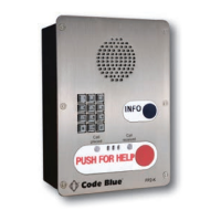
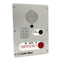
CB 2 Series
Administrator Guide
See diagrams next page
1.0 PRE-INSTALLATION
1.1 Electrical preparation – The unit may have supply wires run from either (a) behind the unit
through the wall, or (b) below the unit using an external conduit through the bottom of the unit.
Holes in the back and bottom of the unit have been provided for this purpose.
2.0 INSTALLATION PROCEDURES
2.1 Remove the top of the unit.
2.2 Mark the mounting holes – In order to comply with the Americans with Disabilities Act (ADA)
of 1990, the speakerphone button(s) should be positioned between 34 and 48 inches from
grade level. (Consult an ADA specialist in your area to verify local and federal guidelines.)
2.3 Drill all marked holes.
2.4 Install the housing – Four anchors of appropriate size and type should be used to fasten the
housing to the wall.
IMPORTANT: If wiring is supplied from the back, ensure that the conduit is aligned at this time.
2.5 Reattach the top.
3.0 ELECTRICAL WIRING
3.1 Ground – The ground (green) wire should be stripped and fastened to the supplied grounding
lug.
3.2 24V AC supply – The unit will contain a 5 nger manifold with corresponding fuses per
component. Incoming power is connected to the red and black wires on the manifold.
3.3 120/240V AC supply – The unit will contain a small 120V AC 40VA transformer. The incom-
ing power would run to the two forks coming off of the transformer and power is distributed
through the 5 nger manifold.
3.4 120,240,277V AC Multi-tap transformer – Incoming power will be connected to the trans-
former and wiring will depend on incoming voltage. A wiring diagram depicting each voltage
option is located on top of the multi-tap transformer. Power will be distributed through the
multiple ngers coming off the transformer.
3.5 PoE Power – The unit will contain a PoE splitter and an IP surge suppressor. The incoming
RJ45 connector would run to the IP surge suppressor inside the unit. A CAT 5 cable from
the surge suppressor runs to the PoE splitter. All power in the unit is distributed through the
PoE splitter.
4.0 COMMUNICATIONS WIRING
4.1 Have category 3 or higher 4-pair cable terminated to a RJ45 applying TIA/EIA T568-B speci-
cations.
18 Legacy CB 2-e with Public Address Installation Instructions