Code Blue
•
259 Hedcor Street
•
Holland, MI 49423 USA
•
800.205.7186
•
www.codeblue.com
GU-149-AApage 40 of 63
CB 2 Series
Administrator Guide
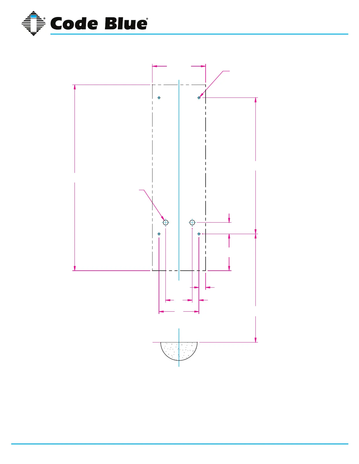
Suggested installation dimensions shown from ground to lower right mounting hole are for single button face-
plates.
• For dual button faceplate, deduct 3.25 inches.
• For keypad faceplate, deduct 4.5 inches.
• For wheelchair direct facing access only, deduct 6 inches.
DISCLAIMER: The dimensions above are intended as guidelines only. For specic installation requirements,
reference your local codes.
30 3/4
43
2 9/16
6
1 1/2
12 REF
9
GROUND/FLOOR
4 X Ø7/16 MOUNTING HOLES
2 X Ø1-1/8
(KNOCKOUTS FOR
Ø3/4 CONDUIT)
42 REF
8 5/16 REF
1 1/2 REF
All wiring must be installed and connected by experienced and certied personnel to meet
local and national electrical codes, and will include a service disconnect.