CODEL
Operation and Maintenance Manual
Issue : A Rev. : 3 Date : 13/11/2018 Ref. : 100351
P a g e | 14
Figure 8: Wiring diagram
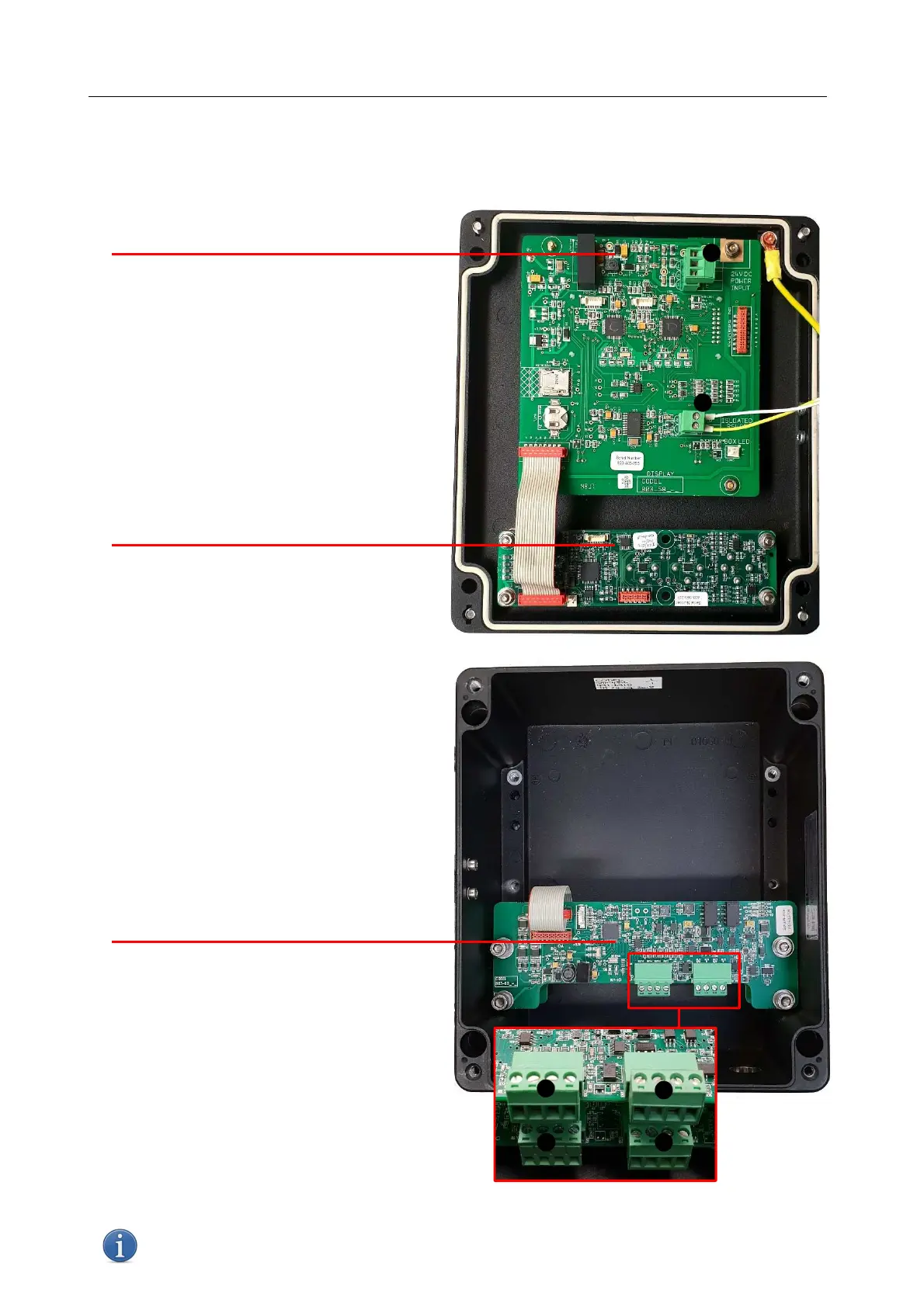
4.2.3 PCB Identification and connections
4.2.3.1 Enclosure Lid
4.2.3.2 Enclosure Base
mA output PCB
mA Board 1 (bottom)
mA Board 2 (top)
① CON6 – mA outputs 1 & 2
② CON3 – Relay outputs 1 & 2
③ CON6 – mA outputs 3 & 4
④ CON3 – Relay outputs 3 & 4
NOTE: The silkscreen for both boards reads: IOUT 1 (mA), IOUT 2, RLY 1 (relay) and RLY 2.
mA and relay 3 and 4 are set to the top PCB via the address rather than the physical board.
❶
❷
Control/Display PCB
① 24VDC Power input
② RS485 communications
Electrochemical Cell (E-Cell) PCB
❶
❷
❷
❶
❸
❹
Figure 9: PCB / Connections identification
 Loading...