26 DataMan 200 Quick Reference Guide DataMan 200 Quick Reference Guide 27
I/O Cable
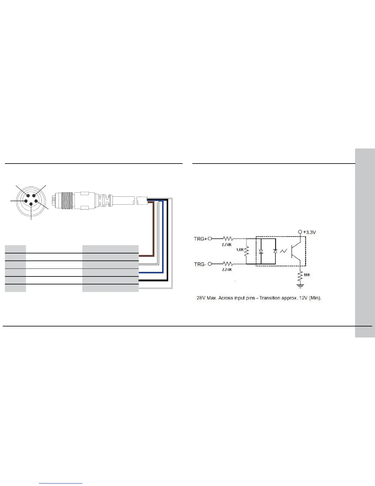
Pin # Signal Name Wire Color
1 High Speed Out 0 Brown
2 High Speed Out 1 White
3 Trigger + Blue
4 Trigger - Black
5 Common Out Grey
1
2
5
3
4
The I/O cable provides access to trigger and high-speed outputs.
Unused bare wires can be clipped short or tied back using a tie made of non-
conductive material.
Note: The RS-232 cable, described on page 32, provides access to the digital
input line (In1).
Acquisition Triggering
The acquisition trigger input on the reader is opto-isolated. To trigger
from an NPN (pull-down) type photo-detector or PLC output, connect
TRG+ to +24V and connect TRG– to the output of the detector. When
the output turns on, it pulls TRG– down to 0V, turning the opto-coupler
on.
To trigger from an PNP (pull-up) photo-detector or PLC output, connect
TRG+ to the output of the detector and connect TRG– to 0V. When the
output turns on, it pulls TRG+ up to 24V, turning the opto-coupler ON.



 To Next Page