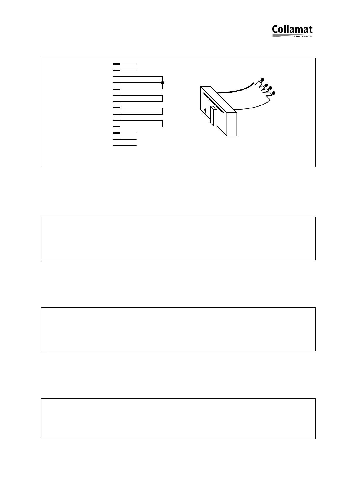
Figure 17 shows the schematic diagram of the diagnostic connector:
Figure 17: Diagnostic connector
Signal display
This test displays the levels of the input signals. It is used to test the function of the sen-
sors and input circuits.
>s
Signals display. Use spacebar to leave
GSC1 GSC2 GSC3 READY LSC NSTPI FAULT
OFF OFF OFF OFF OFF OFF OFF
DIL-switch settings
This test shows the position of the DIL-switches. It is used to test the function of the
DIL-switches.
>d
DIL-switch settings. Use spacebar to leave
TEST DIR DEL NS R1 R2 HOLD
ON OFF OFF OFF OFF OFF OFF
Potentiometer settings
This test shows the position of the potentiometers. It is used to test the function of the
potentiometers.
>p
Potentiometer settings. Use spacebar to leave
SPEED PRE. POS. TCY
1023 0255 0071 0641
nc
nc
nc
nc
nc
1
2
3
4
5
6
7
8
9
11
12
13
14
10
+12V
+12V
FEED
TCY
RESOUT
GND
GND
CLK
GSC1
LSC
READY
GSC2
RESIN
nc
1
14
1
14
5999.527-01A 25.11.98 WM Seite 21 / 32