15
14
Fix the basebar to the steering tube with the nut M5x10 Nut (N.14) from the drive side
and the screw M5x20 (N.15) from the non-drive side. Recommended torque 5 Nm.
After completing the mounting of the basebar and the cable routing, lay the Stem
cover (N.5) on the stem itself, matching the cover front rib with the hole in the
basebar, and x it with screw M3x20 (N.16). Recommended torque max 2 Nm.
NOTE: Always respect the recommended tightening torque on screws, nuts, bolts, and fasteners. Too low torques may lead to unexpected disassembly of components. Too high torques may
lead to thread stripping, deformation and breaking of components. Both situations can cause subassembly failure with consequential losing of vehicle control and fall.
* The presented pictures are for assembly reference only. During complete assembly, hoses and electric cables will be present. Colnago basebar system is compatible with different dual-column
layout extension systems. For the mounting and cable routing of the extension and groupset, follow the instructions provided by specic manufacturers.
7
8
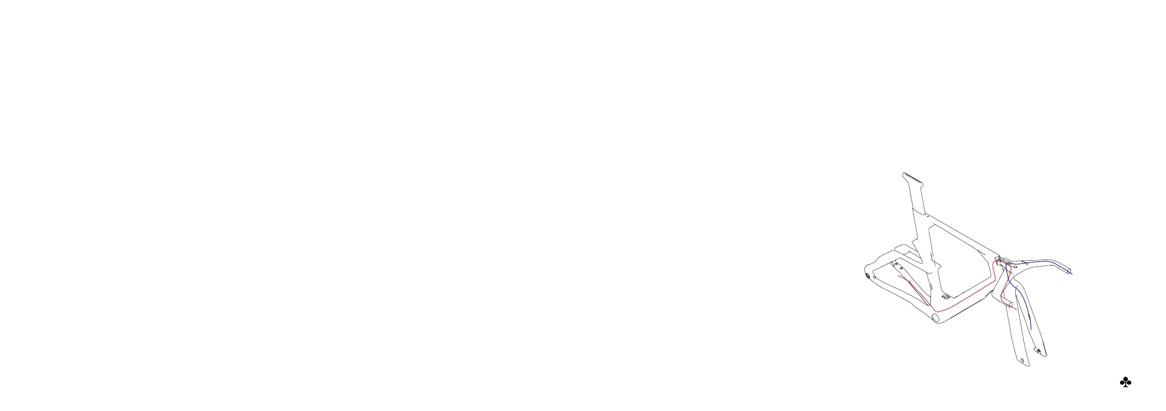
Route the rear brake hose from
chainstay up to the front end of
the top tube, passing through the
bottom bracket area.
Once the hose is inside the frame,
starting from the headset, slightly
wet the inner face of the foam hose
cover (N.29) with some alcohol and
slide it around the rear brake hose.
Route the front brake hose from the
top of the fork up through the fork
front plate, passing through the
hole in the screw N.13.
1
2
3
Brake hose routing
It is recommended that the rear hydraulic brake hose is installed before electric wires. These routing illustrations are intended as a
supplement to the installation instructions only. For each specic brake system, please refer to the component manufacturer’s service
center or website for further information.
(img 7)
 Loading...