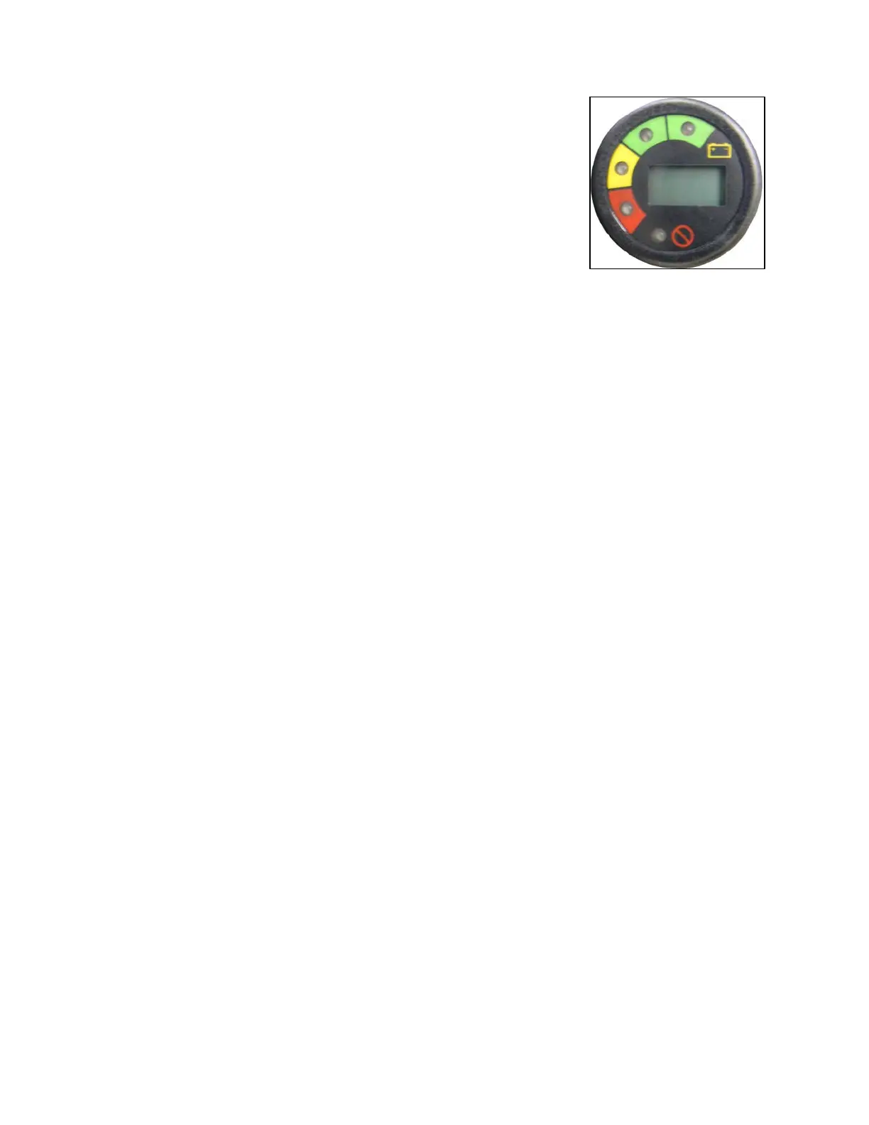
3.3.11A MULTI-FUNCTIONAL DISPLAY INDICATOR (MDI)
Figure 3.3.4 - AC Drive Vehicles only
Located on the support panel in front of the steering wheel. This meter will display
the battery state of charge, an hour meter and the controller status. With fully
charged batteries, the uppermost green LED is lit. A lit lower red LED indicates
discharged batteries. The hour meter is an alpha-numeric liquid crystal display in
the center of the MDI showing the hours worked.
If there is
a controller error the hours worked will be replaced with a flashing error
code. It is important to note the error code. It will aid a technician in corrective
actions.
Figure 3.3.4
3.3.12 TURN SIGNAL/HAZARD WARNING SWITCH - NOT SHOWN
If equipped, the turn signal/hazard warning switch is located on the steering column below the steering wheel. When
lever is moved upward right turn signal turns on. When lever is moved downward left turn signal turns on. To turn off
a signal move indicator lever back to center position.
To operate the hazard warning lights pull outward on hazard bar. Moving the signal indicator lever to either of the turn
signal positions will turn off the hazard lights.
3.3.13 SEAT SWITCH / TRACTION INTERLOCK – NOT SHOWN
Operator must be present in the driver seat for the vehicle traction drive to operate. A reset of the power system is
required if an operator leaves the seat while the accelerator foot pedal is depressed.
3.3.14 WIPER SWITCH - NOT SHOWN
If equipped, the wiper switch is a 3 position toggle switch located on the wiper motor. Up and down locations are the
fast and slow wiper speeds. The middle position is off. When turning wiper to the off position, it auto-positions to the
right side of the windshield.
3.3.15 STEERING WHEEL – NOT SHOWN
The steering wheel controls the path of the vehicle exactly the same as a conventional automobile wheel.
3.3.16 HOUR METER INDICATOR – NOT SHOWN
If equipped, the hour meter is located on the support panel in front of the steering wheel column. It indicates the total
number of hours the vehicle has been operating.
3.3.17 NAMEPLATE – Figure 3.3.1L
Nameplate has important information such as model, vehicle weights and rated capacity (load, operator and
passenger). Do not exceed this capacity. Read carefully.
3.3.18 CONTROLLER LED SYSTEM LIGHT- Figure 3.3.1M
A green LED diagnostic light will indicate a fault in the electrical system. See Section 6.2.
3.4 DRIVING THE VEHICLE
Complete the following PRE-OPERATION CHECKLIST.
Insert key and turn key to "ON" position.
Switch the direction selector to the direction of desired travel.
Slowly press the toe of the accelerator/brake pedal to obtain desired vehicle speed.
To slow or stop, remove pressure from the accelerator/brake pedal.
BC 2012
3-4