Manual FLOW 38 Page 9 (total 54) COMAC CAL s.r.o.
Actual installation in pipeline
When welding both counter-flanges to the pipelines, it is necessary to maintain their alignment so that
levelness of bearing surfaces of the flanges onto the front faces of the detector is ensured (at the same
time, this must not be achieved by unequal tightening of the bolts as there is a risk of leakage due to
thermal loading in the future or the measuring tube may break during such tightening). The difference
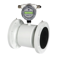
of L
MAX
and L
MIN
distances of the sealing surfaces of the flanges before the flow sensor is installed
must not be greater than 0.5 mm.
The opposition of the holes in the counter-flanges for the bolts should be ensured in the same manner
and a sufficient room behind the flanges should be available for the bolts and nuts so that the actual
installation of the sensor in pipeline and its attachment with the bolts is made possible.
The manufacturer recommends using an intermediate piece during welding. It is absolutely excluded to
use the flow sensor as an intermediate piece due to thermal damage. The welding current must not run
through the flow sensor during electrical welding. The installation of the flow sensor is carried out after
welding, coating, building and similar works are completed.
The actual installation is performed by the fixation between the counter-flanges that are welded to the
calming pipeline (5×d before and 3×d after in the direction of flow) whereas the liquid must run through
the flow sensor in the direction indicated by the arrow on the sensor name plate.
During installation, do not lift the meter by the evaluation unit housing (in case of detached design, by
the sensor terminal box), possibly under the meter's metallic housing but always use slings round the
process connection or use the lifting lugs on the flanges.
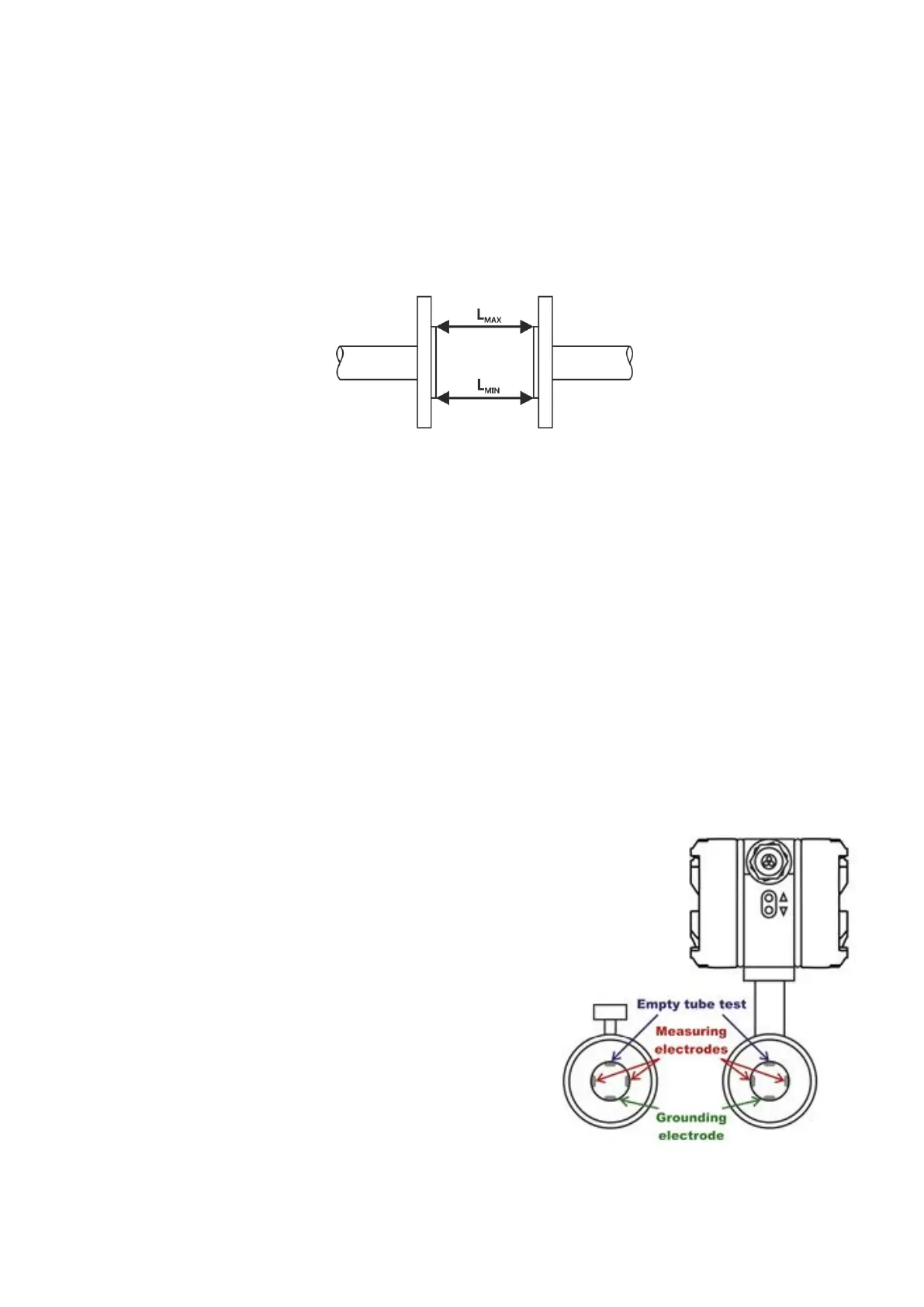
Installation position
The inductive flow sensor is installed in arbitrary position in
vertical piping. In case of horizontal piping, it is necessary to
make sure that the sensor is installed with its measuring
electrodes in horizontal position. In case of the earthing
electrode design, possibly with testing for empty pipeline, then
the installation is always performed with the earthing
reference electrode facing down (with the sensor terminal box,
eventually with the evaluation unit facing upwards). Then the
earthing reference electrode is in the bottom position and the
empty tube sensing electrode is in the top position of the flow
sensor.
Every time when the empty tube testing electrode is not
covered with a liquid for 5sec at least, the flow meter will
display the "Empty tube" status, and if it is necessary, it sends
out an error message and stops taking measurement.