Do you have a question about the ComAp InteliNano MRS 3 and is the answer not in the manual?
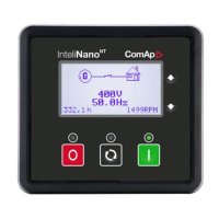
First screen displays basic info (voltage, frequency, GCB status, RPM) and alarm symbol.
Displays detailed info: voltage, frequency, current, power, senders, energy, alarms.
Every event listed is saved in history with running hours stamp.
Covers active and inactive warnings, their indicators, and confirmation status for alarms.
Details shutdown procedures and states (active/inactive, confirmed/unconfirmed).
Explains diagnostic messages (SPN/FMI) and references for further info.
Explains starting and stopping the engine using START/STOP buttons in Manual mode.
Explains AUTO mode where start/stop is automatic, not manual.
The InteliNanoNT MRS 3 is a compact gen-set controller designed for single small gen-set applications, particularly suitable for prime-power scenarios. This device provides comprehensive control and monitoring capabilities for generator sets, ensuring reliable operation and protection.
The primary function of the InteliNanoNT MRS 3 is to manage the operation of a single gen-set. It acts as the central control unit, overseeing the engine's start and stop sequences, monitoring various parameters, and responding to alarms and events. The controller supports both manual and automatic operating modes, offering flexibility in how the gen-set is managed. In manual mode, an operator can directly initiate start and stop procedures, while in auto mode, the controller autonomously manages the gen-set based on predefined conditions and remote commands.
A key aspect of its functionality is the display of critical operational data. The controller's graphic B/W display (128x64 pixels) presents information in a structured manner, organized into multiple screens. These screens provide real-time data on voltage, frequency, current, power (real and apparent), power factor, oil pressure, coolant temperature, fuel level, and battery voltage. This detailed information allows operators to quickly assess the gen-set's status and performance.
The InteliNanoNT MRS 3 also incorporates robust alarm and event management. It categorizes issues into events, warnings, shutdowns, and ECU messages, each with distinct behaviors and implications for gen-set operation. Warnings indicate potential problems that require attention but do not immediately stop the engine, while shutdowns are critical faults that trigger an immediate engine stop to prevent damage. ECU messages provide diagnostic information directly from the engine's Electronic Control Unit, aiding in troubleshooting. The controller records these alarms and events in a history log, complete with running hours stamps, enabling operators to review past incidents and identify trends.
For engine control, the device includes dedicated outputs for key components such as the GCB (Generator Circuit Breaker), starter, prestart, fuel solenoid, and stop solenoid. These outputs are activated or deactivated based on the operating mode and detected conditions, ensuring proper engine sequencing and protection. The controller can also receive remote start/stop commands via binary inputs, enhancing its integration into broader control systems.
The InteliNanoNT MRS 3 is designed for ease of use, featuring an intuitive operator interface with clearly labeled buttons and a structured display.
The front panel includes several buttons for control and navigation:
Information is presented across multiple screens, which can be navigated using the up and down buttons.
The controller provides clear visual indicators for alarms and events.
The InteliNanoNT MRS 3 offers several features that aid in maintenance and troubleshooting:
Detailed History Records: The comprehensive history log is invaluable for maintenance. By reviewing past events, warnings, shutdowns, and ECU messages, technicians can identify recurring issues, understand the sequence of events leading to a fault, and diagnose problems more efficiently. Each record includes a running hours stamp, providing context for when the incident occurred relative to the gen-set's operational lifespan.
ECU Messages: The ability to display diagnostic messages directly from the engine's ECU (Electronic Control Unit) is a significant maintenance advantage. These messages, typically presented as J1939 SPN (Suspect Parameter Number) and FMI (Failure Mode Identifier) codes, provide specific information about engine faults. Technicians can refer to SAE HS-1939 publications or the engine manufacturer's error code lists to interpret these codes, pinpointing the exact nature of an engine problem. This reduces diagnostic time and ensures that the correct repairs are performed.
Visual Indicators for Alarms: The distinct blinking and solid states of the red alarm LED, along with the alarm symbols on the display, provide immediate visual cues about the gen-set's health. This allows operators to quickly determine if a warning or a critical shutdown has occurred, guiding them to investigate further. The distinction between active unconfirmed and active confirmed shutdowns helps in understanding the current state of a fault and whether the engine can be restarted.
Monitoring of Key Parameters: Continuous monitoring of parameters such as oil pressure, coolant temperature, fuel level, and battery voltage helps in proactive maintenance. Deviations from normal operating ranges for these parameters can indicate impending issues, allowing technicians to intervene before a major failure occurs. For example, a consistently low oil pressure warning might prompt an oil level check or a system inspection.
Running Hours Counter: The integrated running hours counter is essential for scheduling routine maintenance tasks, such as oil changes, filter replacements, and major overhauls, based on the gen-set's actual operational time. This ensures that maintenance is performed at appropriate intervals, extending the lifespan of the gen-set and preventing unexpected breakdowns.
Structured Display of Information: The organization of information into multiple screens, including detailed voltage, current, and power measurements, allows maintenance personnel to thoroughly evaluate the gen-set's electrical performance. This is crucial for identifying issues related to load balancing, power quality, or generator output.
Overall, the InteliNanoNT MRS 3 is a robust and user-friendly controller that simplifies the operation, monitoring, and maintenance of small gen-sets, making it an ideal choice for prime-power applications where reliability and efficient management are paramount.
| Model | InteliNano MRS 3 |
|---|---|
| Supply voltage | 8-36 V DC |
| Operating temperature | -20 to +70 °C |
| Generator frequency | 50/60 Hz |
| Communication Ports | RS485 |
| Operating temperature range | -20°C to +70°C |
| Protection class | IP65 |
| Supported protocols | Modbus |
| Input voltage range | 8-36 V DC |