4
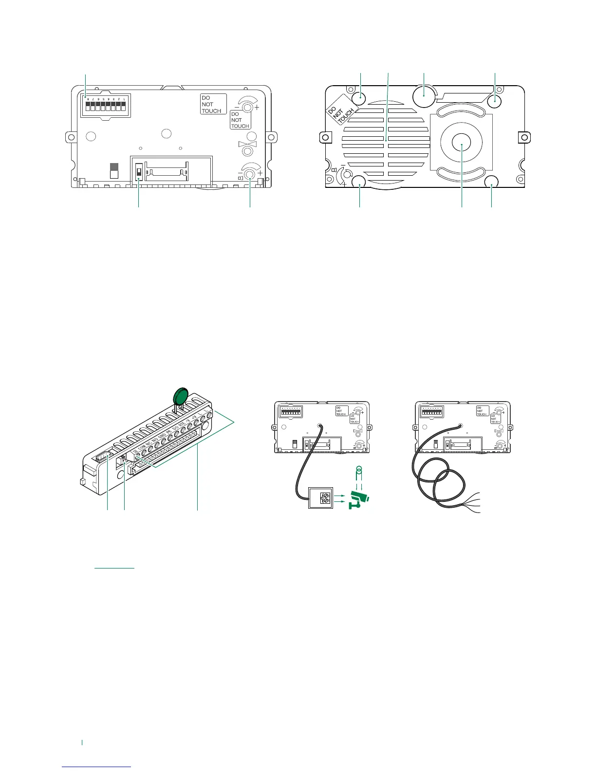
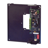
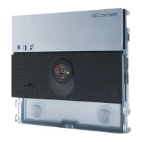
1. DIP switches for function programming and setting the
user code.
2. Switch for confirming special programmes.
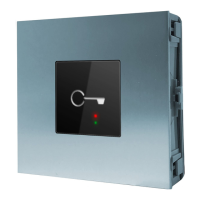
3. Loudspeaker volume control.
4. Indicator LED: call sent.
5. Loudspeaker.
6. Microphone.
7. Indicator LED: system busy.
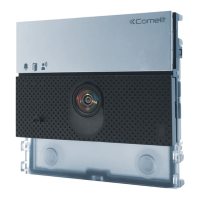
8. Indicator LED: sound activated.
9. Colour camera (with Art. 4680C only).
10. Indicator LED: lock-release activated.
11. 8-pole cable connector.
12. RC network control for door lock filter on relay contacts
(see “Variants”).
13. Terminal block for connection:
SE electric lock connection
COM common relay contact
NC normally closed relay contact
NO normally open relay contact
GND input reference negative for DO-RTE
PR programming input
DO door opened signal input
RTE local lock release input
V- power supply negative
V+ power supply positive
LL bus line connection
Connecting the remote camera
Art. 1622VC is supplied with a cable for the connection of a
separately powered remote camera.
Art. 1622VCF is supplied with a cable for the connection of a
camera powered by the external unit (12 V-150 mA MAX).