Do you have a question about the Comelit 4682HD and is the answer not in the manual?
Product designed for audio/video communication systems in residential, commercial, industrial, and public buildings.
Installation must be performed by qualified technical personnel following provided instructions.
Disconnect power before wiring; use appropriate cross-section wires and avoid shared ducts with power cables.
Observe manual instructions and ensure system integrity for safe operation.
Routine cleaning only; repairs must be done by Comelit or qualified personnel.
Comelit Group S.p.A. is not liable for misuse or failure to follow warnings.
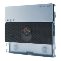
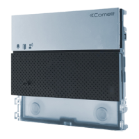
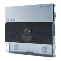
Compatibility of Art. 4682HD with Ikall, Ikall Metal, Vandalcom, and Roma series external units.
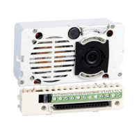
Details audio/video systems, camera, viewing angle, video encoding, sensor, signal/noise ratio, power, consumption.
Covers video resolution and multistream management features.
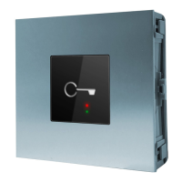
Details the key button function.
Describes visual, acoustic indications, and voice synthesis.
Covers loudspeaker and microphone volume adjustments via ViP Manager.
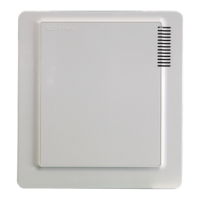
Provides product dimensions: height, width, and depth.
Confirms compatibility with ViP system and video entry family.
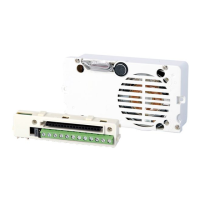
Specifies wired connectivity via Ethernet ports.
Details rated voltage and current for relay outputs and electronic locks.
Wiring diagram for connecting the module using a POE power supply.
Diagram for connecting the module with an additional power supply (Art. 1595).
Wiring diagram for a variant using the external unit relay.
Wiring diagram for a variant using a safety lock.
Table listing consumption values for various Ikall, Vandalcom, and Single-plate modules.
Wiring diagram for connecting Ikall button modules.
Wiring diagram for connecting Art. 3360B and 3360BM modules.
Wiring diagram for connecting Art. 3064S and Art. 1172B modules.
Wiring diagram for connecting Art. 3188SB modules.
Wiring diagram for connecting Art. 3063D with additional power supply.
Wiring diagram for connecting Simplekey readers Art. SK90001 and SK90011.
Procedure for assigning index numbers to additional button modules using dip switches.
| Brand | Comelit |
|---|---|
| Model | 4682HD |
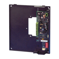
| Category | Control Unit |
| Language | English |