EasyManua.ls Logo

Comelit 5714C User Manual

Comelit 5714C
12 pages
To Next Page IconTo Next Page
Page #1 background imageLoading...
Page #1 background image
PT
MANUAL
TÉCNICO
IT
MANUALE
TECNICO
EN
TECHNICAL
MANUAL
FR
MANUEL
TECHNIQUE
NL
TECHNISCHE
HANDLEIDING
DE
TECHNISCHES
HANDBUCH
ES
MANUAL
TÉCNICO
Assistenza tecnica Italia 0346/750090
Commerciale Italia 0346/750091
Technical service abroad (+39)0346750092
Export department (+39) 0346750093
www.comelitgroup.com
Integrazione FT SBC 04
Supplement for FT SBC 04
Intégration FT SBC 04
Aanvulling FT SBC 04
Ergänzung zu FT SBC 04
Integración FT SBC 04
Integração FT SBC 04
Question and Answer IconNeed help?

Do you have a question about the Comelit 5714C and is the answer not in the manual?

Comelit 5714C Specifications

General IconGeneral
CategoryControl Unit
Model5714C
BrandComelit
TypePower supply unit
Power Supply12V DC
MaterialPlastic
ColorWhite
SeriesComelit
SystemVideo Intercom

Summary

Bracket Art. 5714C

CV5 Jumper for video closure

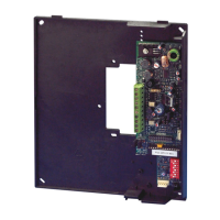
Jumper for video closure.

DL1 Red LED indicating programming status

Red LED indicating programming status.

S1 User code programming microswitches

Microswitches for user code programming.

S2 Microswitches for programming buttons and functions

Microswitches for buttons and functions.

CN1 Connector for optional cards

Connector for optional cards Art. 5733, 5734.

CN2 Connector for reading configuration

Connector for configuration reading & programming mode.

JP1 Jumper to set bracket as main or secondary

Jumper to set bracket as main (M) or secondary (S).

CV3 CV4 Jumper for freeing button 1

Jumper for freeing button 1 (C. NO. contact).

Monitor-bracket connector

Monitor-bracket connector.

System connection terminals

Terminals for system connection (+20 OV, LL, CFP).

CV8 in position for +AL LED as LED or ALARM

Jumper for +AL LED as LED (default) or ALARM.

CV1 CV2 CV7 Additional monitor power supply jumpers

Jumpers for additional monitor power supply.

Bracket Art. 5714C Performance Expansion

Management of alarm signal to switchboard

Manages alarm signal from external contact or internal button.

Programming button and intercom functions

Programs button/intercom functions without handheld programmer.

General intercom call to all internal units

Enables general or selective intercom calls without dedicated interface.

Main switchboard call

Enables call to the main switchboard.

Programming Buttons and Functions

Button Programming Legend

Legend for button programming options (A, ACT, AL, AI, CCP, CCS, K, D).

Button Programming Settings

Configuration examples for buttons using DIP switches and jumpers.

Programming Notes

Instructions to note and restore S2, S1, JP1 settings after programming.

Additional Programming

Supplementary Programming

Instructions for supplementary programming tasks.

Setting Codes for Tabs A and B

Procedure for setting codes using TAB. A and TAB. B.

Programming Notes

Instructions to note and restore S2, S1, JP1 settings after programming.

Intercom Programming

Intercom Address Programming

Procedure for setting and deleting intercom addresses.

Intercom Call Programming

Programming intercom calls using buttons and TAB. A.

Programming Notes

Instructions to note and restore S2, S1, JP1 settings after programming.

Programming Reset and Direct Call

Programming Reset

Factory settings for buttons, LEDs, and intercom addresses.

Direct Programming of Intercom Call

Enables direct programming of intercom calls from internal units.

Using Button P1 as an actuator

Defines the function of Button P1 as an actuator or relay.

Alarm and LED Functions

LED Indication Input

Using +AL LED contact as input for LED signaling.

Alarm Input Function

Using +AL LED contact as input for alarm signaling.

Selective Intercom System Diagram

Related product manuals