Do you have a question about the Comelit Ultra Simplebus2 and is the answer not in the manual?
Defines the product's application scope for residential, commercial, industrial, and public buildings.
Emphasizes qualified personnel and adherence to manual instructions for installation.
Advises disconnecting power before wiring and using appropriate cross-section wires.
Highlights adherence to manuals and ensuring system integrity for safe operation.
Specifies routine cleaning and exclusively Comelit-authorized repairs.
States Comelit's non-responsibility for misuse or non-compliance with manuals.
Declares conformity to applicable EU directives and WEEE disposal guidelines.
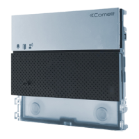
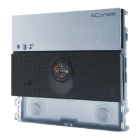
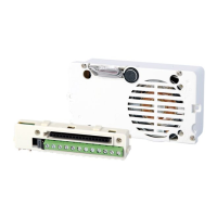
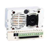
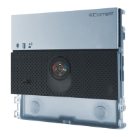
Detailed description of the audio module, its features, and dimensions.
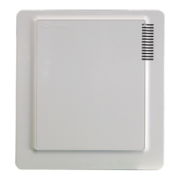
Overview of ULTRA panel variants and available finishes.
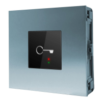
Explanation of the status indicators for call, lock-release, and system busy.
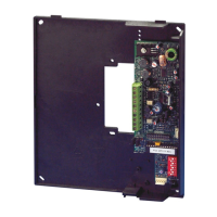
Description of connections for RTE, GND, SE, power, and bus lines.
Covers type, dimensions, color, weight, and materials of the product.
Lists supported Comelit Simplebus 2 system configurations.
Details microphone and loudspeaker characteristics.
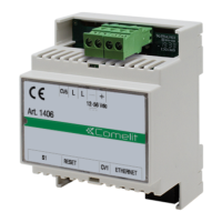
Provides voltage, absorption, and power supply details.
Outlines button types, backlighting, terminals, and output types.
Configuration options for volume and backlighting.
Methods for programming: manual via DIP switch or VIP Manager software.
IP/IK ratings, operating temperature, humidity, and certifications.
Lists core functionalities like lock-release, auxiliary relays, and system status indications.
Tables detailing components for flush-mounted and surface-mounted installations.
Step-by-step guide for installing the flush-mounted box and modules.
Instructions for assembling and wiring boxes when installed adjacent to each other.
Procedure for mounting the external unit onto a wall.
Details on writing on nameplates or applying adhesive labels and printing guides.
Step-by-step guide for removing nameplates and the module from the housing.
Illustrates the basic wiring for standard system setup.
Shows how to connect the system with an auxiliary power supply.
Details wiring for outdoor entrance panel relay and safety door lock.
Table detailing absorption (W) for various entrance panel modules.
Guidelines on power limits and using supplementary power supplies.
Wiring diagrams for UT9200, UT9270, and UT9279M modules.
Diagram illustrating the connection for the UT9260M digital directory module.
Setting the button type for normal operation (single/dual).
Assigning unique addresses to button modules for recognition.
Explains consecutive and specific user code programming.
Step-by-step guide for assigning sequential user codes to buttons.
Detailed steps for assigning unique, non-sequential user codes to buttons.
Procedure for setting DIP switches for special functions.
Reference table for DIP switch codes and functions.
Covers reset wait times, button tones, backlighting, and restore functions.
Configuring button LEDs using the twilight sensor (OFF, ON, AUTO).
Procedure to verify the twilight sensor's AUTO mode functionality.
Steps to enable brightness control and adjust individual button LED levels.
Illustrates how Light-Me interacts with OFF, ON, and AUTO backlighting modes.
Steps to replace an audio module and restore programming settings.
Using ViP Manager software for device configuration via USB.
Troubleshooting guide for LED indications and deterrent tones.
Diagrams showing typical system configurations with various devices.
Table detailing maximum cable lengths for different wire types and systems.
Information on the maximum number of devices and users per system.
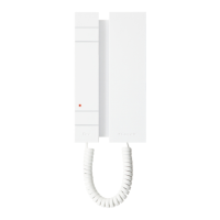
Limits on internal units per user code within an apartment.
Diagram illustrating the wiring of multiple devices in a system.
Guidance on system performance and installation layouts for Simplebus2 audio.
Comprehensive table linking DIP switch settings to user codes.
| Brand | Comelit |
|---|---|
| Model | Ultra Simplebus2 |
| Category | Control Unit |
| Language | English |