Do you have a question about the Comelit UT8020 and is the answer not in the manual?
Product designed for audio/video communication systems in residential, commercial, industrial, public buildings.
Installation by qualified personnel following manual instructions.
Disconnect power, use correct cross-section wires, avoid shared ducts with power cables.
Observe manual, ensure system is not tampered with or damaged.
Routine cleaning only, repairs by Comelit or qualified personnel.
Comelit not responsible for unintended use or failure to follow instructions.
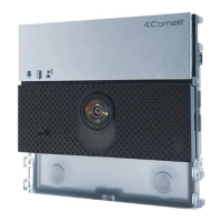
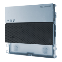
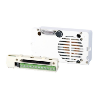
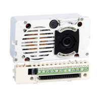
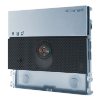
Audio/video module for Ultra entrance panel, IP (ViP) system. Features include twilight sensor, omnidirectional mic, dual speakers, wide-angle camera.
Product type, dimensions, color, materials, mounting options.
Microphone and loudspeaker details, echo cancelling.
Camera type and viewing angle.
Power supply type and PoE class.
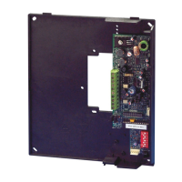
Call type, buttons, terminals, inputs/outputs, communication port.
Loudspeaker/mic volume, backlighting, viewing area adjustments.
LAN type and IP address assignment.
ViP Manager software usage.
Operating temperature and humidity.
Lock-release, auxiliary relays, inputs, status indications, voice synthesis.
Table showing components for flush-mounted installations with various boxes, shields, and frames.
Table showing components for surface-mounted installations with various housings and frames.
Step-by-step guide for flush-mounting the entrance panel.
Guidance on installing multiple units adjacent to each other.
Step-by-step guide for wall-mounting the entrance panel.
Wiring diagram for connecting to a 1440 unit.
Wiring diagram for connecting to a standard POE switch.
Wiring diagrams for using separate power supply units 1595 or 1596B.
Wiring diagram for non-POE switch with separate power supply.
Configuration for using an external relay.
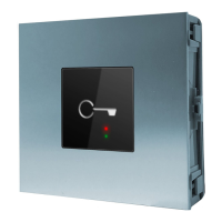
Configuration for integrating a safety door lock.
Table detailing maximum power available for modules based on power supply type.
Table listing absorption power for various entrance panel modules.
Diagram showing connections for button modules.
Diagram showing connections for touchscreen modules.
Diagram for touchscreen module with extra power supply.
Diagram showing connections for number keypad modules.
Procedure for assigning addresses to button modules using DIP switches.
Description of the initial startup process and LED behavior.
Steps to adjust the brightness of individual button LEDs.
Procedure to restore the module to its default factory settings.
Information on maximum cable lengths for different connection types.
Guide to configuring devices using ViP Manager software.
| Model | UT8020 |
|---|---|
| Type | Control unit |
| Operating Temperature | -10°C to +55°C |
| Humidity | 90% non-condensing |
| Material | Plastic |