22
1
ON
2 3 4 65
ON
1 2 3 4 65
ON
1 2 3 4 65
ON
1 2 3 4 65
ON
1 2 3 4 65
ON
1 2 3 4 65
1
2
4
3
5
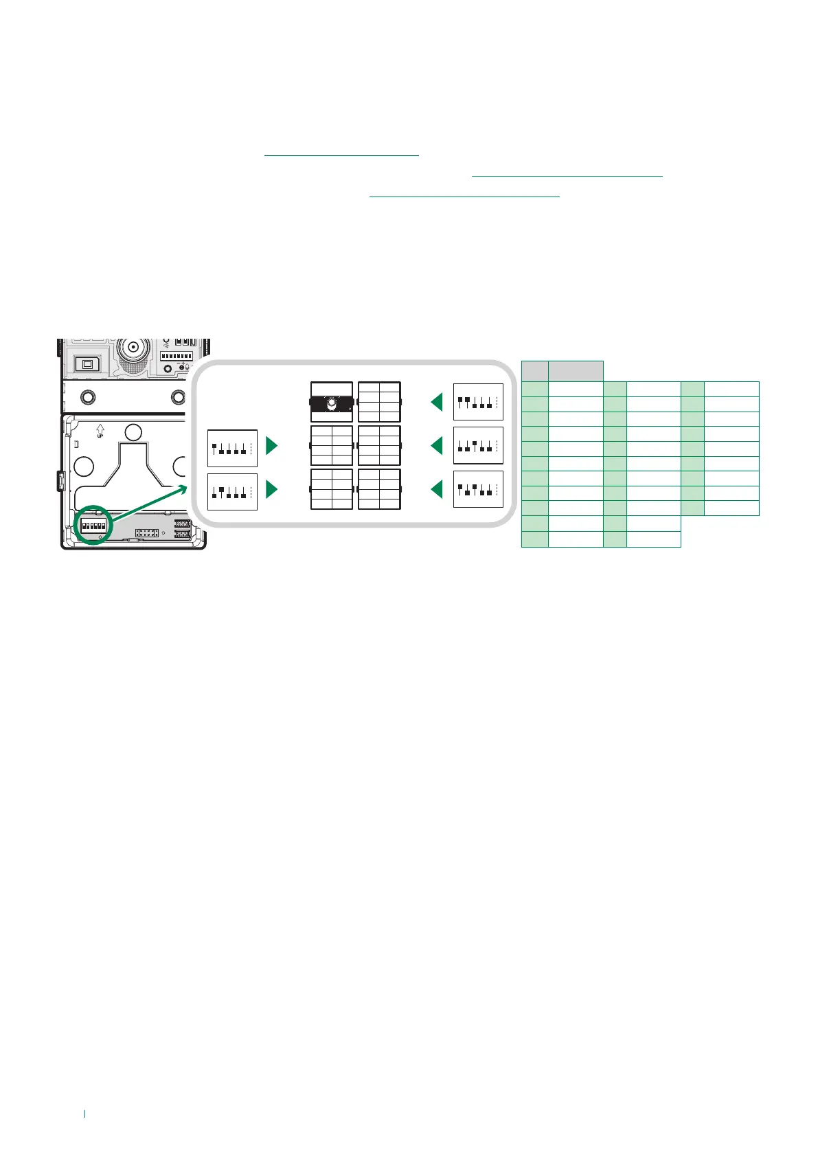
Programming
code
DIP ON
1 1 12 3.4 23 1,2,3,5
2 2 13 1,3,4 24 4.5
3 1.2 14 2,3,4 25 1,4,5
4 3 15 1,2,3,4 26 2,4,5
5 1.3 16 5 27 1,2,4,5
6 2.3 17 1.5 28 3,4,5
7 1,2,3 18 2.5 29 1,3,4,5
8 4 19 1,2,5 30 2,3,4,5
9 1.4 20 3.5 31 1,2,3,4,5
10 2.4 21 1,3,5
11 1,2,4 22 2,3,5
TAB. A
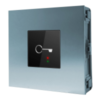
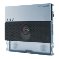
Address button modules
First startup or restarting
DIP 1-5: addressing call button module (see TAB. A)
Addressing call button modules means that, in the event they are replaced, it is not necessary to reprogram the button
addresses. All you need to do is assign the same address as before to the new module.
When starting up the module (30 sec. approx.):
f the button backlighting comes on
f the red LED flashes
» At the end of the startup process the red LED switches off and the backlighting behaves according to its configuration.
To perform programming correctly, proceed as follows:
I. Address the button modules (see “Address button modules”)
II. Configure the ViP address for the UT8020 module via ViP Manager (see“Programming via ViP Manager”)
III. Program the ViP call addresses via ViP Manager (see“Programming via ViP Manager”)