2
12
11
10
9
8
7
6
5
1
2
3
4
IT
EN
FR
NL
DE
ES
PT
IT
EN
FR
NL
DE
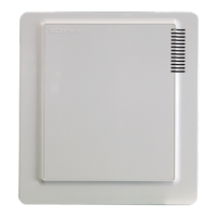
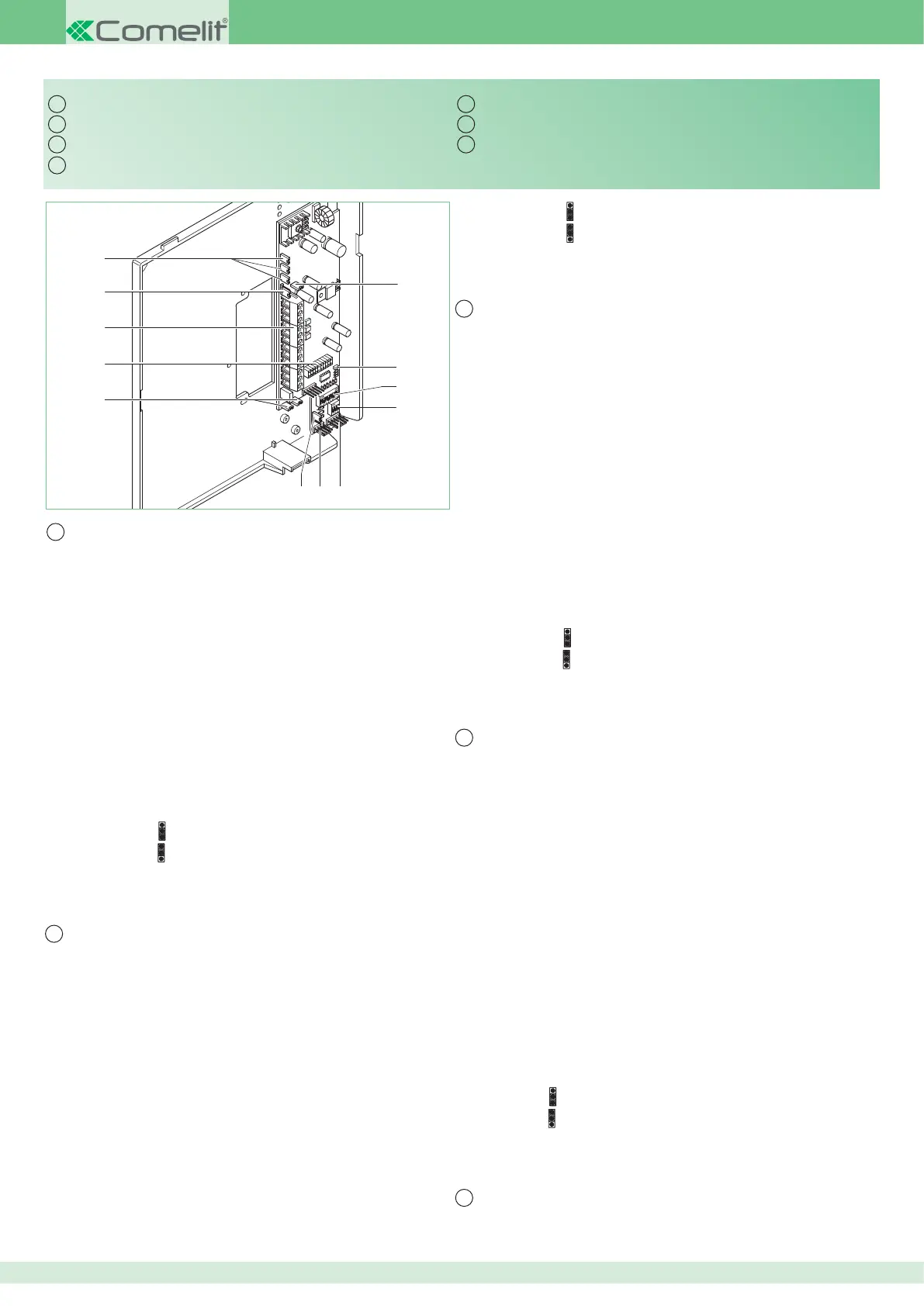
Staffa Art. 5714C
1 CV5 Jumper chiusura video.
2 DL1 Led rosso segnala lo stato di programmazione.
3 S1 Micro-interruttori per programmazione codice utente.
4 S2 Micro-interruttori per programmazione pulsanti e funzioni (vedi tabelle pag. 5, 6, 7).
5 CN1 Connettore per schede opzionali Art. 5733, Art. 5734.
6 CN2 Connettore per lettura configurazione con Art. 1251/A e per ingresso in modalità di
programmazione.
7 JP1 Jumper per programmare la staffa come principale (P) o secondaria (S).
8 CV3 CV4 Jumper per liberare Pulsante 1 (contatto C. NO. 24V-100mA max).
9 Connettore Staffa-Monitor.
10 Morsetti connessione impianto:
+20 0V Morsetti per connessione con Art. 1205/B o 1212/B.
L L Connessione alla linea bus.
CFP Ingresso chiamata da piano.
CFP + Ingresso chiamata da piano o allarme (vedi variante SB2/A18BC, pag. 11).
P1 C1 Morsetti Pulsante 1 per servizi vari.
Per avere un contatto C.NO. (24V-100mA max) rimuovere i jumper CV3 e CV4.
S+ S- Morsetti per dispositivo ripetizione di chiamata.
+LED AL Morsetto ingresso LED per servizi vari o allarme (vedi variante SB2/A17BC, pag. 11).
LED- Morsetto ingresso LED per servizi vari.
11 CV8 in posizione per l'utilizzo del contatto +LED AL come LED (di default);
in posizione
per l'utilizzo del contatto +LED AL come ALLARME.
12 CV1 CV2 CV7 Jumper alimentazione Monitor aggiuntivo.
Per informazioni complete su impianti Simplebus Color (che utilizzano quindi il
miscelatore/alimentatore Art. 4888C) fare riferimento al manuale tecnico MT/SBC/01.
Bracket Art. 5714C
1 CV5 Jumper for video closure.
2 DL1 Red LED indicating programming status.
3 S1 User code programming microswitches.
4 S2 Microswitches for programming buttons and functions (see tables, page
5, 6, 7
).
5 CN1 Connector for optional cards Art. 5733, Art. 5734.
6 CN2 Connector for reading configuration with Art. 1251/A and for input in
programming mode.
7 JP1 Jumper to set bracket as main (M) or secondary (S).
8 CV3 CV4 Jumper for freeing button 1 (contact C. NO. 24V-100mA max).
9 Monitor-bracket connector.
10 System connection terminals:
+20 0V Terminals for connection to Art. 1205/B or 1212/B.
L L Bus line connection.
CFP Floor door call input.
CFP + Floor door call or alarm input (see variant SB2/A18BC, page 11).
P1 C1 Terminals of button 1 for various purposes.
To have a C.NO. contact (24V-100mA max), remove jumpers CV3 and CV4.
S+ S- Terminals for call repetition device.
+AL LED LED input terminal for various purposes or alarm (see variant SB2/
A17BC, page 11).
LED- LED input terminal for various purposes.
11 CV8 in position
for using the +AL LED contact as LED (default);
in position
for using the +AL LED contact as ALARM.
12 CV1 CV2 CV7 Additional monitor power supply jumpers.
For further information about Simplebus Color systems (systems which use mixer-
power supply Art. 4888C) please see Technical Manual MT/SBC/01.
Étrier Art. 5714C
1 CV5 Cavalier débranchement vidéo.
2 DL1 La led rouge signale l'état de programmation.
3 S1 DIP switches pour la programmation du code usager.
4 S2 DIP switches pour la programmation des boutons et fonctions (voir tableaux pages
5, 6, 7
).
5 CN1 Connecteur pour cartes en option Art. 5733, Art. 5734.
6 CN2 Connecteur pour lecture configuration avec Art. 1251/A et pour entrée en modalité
de programmation.
7 JP1 Cavalier pour programmer l'étrier comme Principal (P) ou Secondaire (S).
8 CV3 CV4 Cavalier pour libérer le bouton 1 (contact C. NO. 24V-100mA maxi).
9 Connecteur Étrier-Moniteur.
10 Bornes pour le raccordement de l'installation :
+20 0V Bornes de connexion avec Art. 1205/B ou 1212/B.
L L Connexion à la ligne bus.
CFP Entrée appel du palier.
CFP + Entrée appel du palier ou alarme (voir variante SB2/A18BC, page 11).
P1 C1 Bornes Bouton 1 pour services divers.
Pour avoir un contact C.NO. (24V-100mA maxi) enlever les cavaliers CV3 et CV4.
S- S+ Bornes pour le dispositif de répétition de l'appel.
+LED AL Borne entrée LED pour services divers ou alarme (voir variante SB2/A17BC,
page 11).
LED- Borne entrée LED pour services divers.
11 CV8 en position pour l'emploi du contact +LED AL comme LED (par défaut) ;
en position pour l'emploi du contact +LED AL comme ALARME.
12 CV1 CV2 CV7 Cavalier d'alimentation du moniteur supplémentaire.
Pour plus d'informations relatives aux installations Simplebus Color (qui utilisent le
mélangeur/alimentateur Art. 4888C) voir le manuel technique MT/SBC/01.
Grondplaat Art. 5714C
1 CV5 Jumper voor het afsluiten van het videosignaal.
2 DL1 Rode led signaleert de programmeerstatus.
3 S1 Microschakelaars voor programmering van de gebruikerscode.
4 S2 Microschakelaars voor de programmering van de knoppen en functies (zie de tabellen
op pag. 5, 6, 7).
5 CN1 Connector voor optionele kaarten Art. 5733, Art. 5734.
6 CN2 Connector voor het lezen van de configuratie met Art. 1251/A en voor de toegang tot
de programmeermodus.
7 JP1 Jumper voor het programmeren van de grondplaat als hoofdgrondplaat (P) of
secundaire grondplaat (S).
8 CV3 CV4 Jumpers voor het vrijmaken van drukknop 1 (C. NO.-contact max. 24V-100mA).
9 Connector voor grondplaat van monitor.
10 Aansluitklemmen voor de installatie:
+20 0V Klemmen voor aansluiting op Art. 1205/B of 1212/B.
L L Aansluiting op busleiding.
CFP Ingang voor etagebel.
CFP + Ingang voor etagebel of alarm (zie variant SB2/A18BC, pag. 11).
P1 C1 Klemmen knop 1 voor verschillende functies.
Om over een C.NO.-contact (max. 24V-100mA) te kunnen beschikken, de jumpers
CV3 en CV4 verwijderen.
S- S+ Klemmen voor aansluiting van extra bel.
+LED AL Klem ingang led voor verschillende functies of alarm (zie variant SB2/A17BC,
pag. 11).
LED- Klem ingang led voor verschillende functies.
11 CV8 in stand voor het gebruik van het contact +LED AL als LED (standaard);
in stand voor het gebruik van het contact +LED AL als ALARM.
12 CV1 CV2 CV7 Jumpers voor voeding van extra monitor.
Raadpleeg voor verdere informatie over Simplebus Color-systemen (met mixer/
voedingstransformator Art. 4888C) de technische handleiding MT/SBC/01.
Grundplatte Art. 5714C
1 CV5 Stecker für Ausschaltung des Videosignals.
2 DL1 Rote Anzeige-LED des Programmierstatus.
3 S1 Mikroschalter zur Programmierung des Teilnehmercodes.
4 S2 Mikroschalter zur Programmierung von Tasten und Funktionen (siehe die
Placa soporte Art. 5714C
Suporte Art. 5714C
 Loading...