B A
PR
1. 2.
3.
4
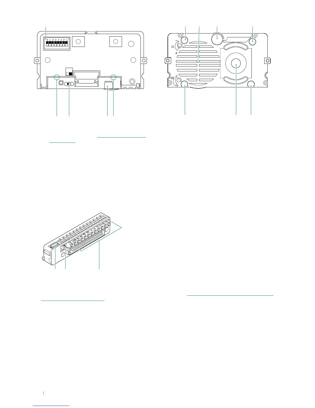
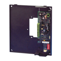
1. Programming DIP-switch for button module indexing
and Device reset
2. Power supply indicator LED
3. PR switch for input/output programming
A in programming mode
B normal operation
4. Connector for magnetic induction audio amplification
module connection
5. Ethernet port activity indicator LED
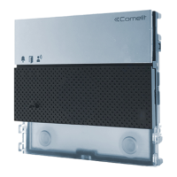
6. Indicator LED: call sent
7. Speaker.
8. Microphone.
9. Indicator LED: system busy
10. Indicator LED: sound activated
11. Colour camera.
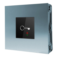
12. Indicator LED: lock-release activated
1. Connector for 8-core wire for button module connection
2. JP1 manages the RC network for door lock filter on the relay contacts (see “Variant for using the external unit relay /
Variant for using a safety lock”)
3. Terminal block for connection:
SE+ connection for electric door lock
COM relay common contact
NC relay normally closed contact
NO relay normally open contact
GND SE- RTE input and SE door lock reference negative
RTE local lock-release input
V- V+ +33V or PoE power supply
TX- TX+ Ethernet transmission line terminals
RX- RX+ Ethernet receiving line terminals