AMIGA 1000 ASSEMBLY LEVEL REPAIR
3.5 BEZEL AND CASE INSTALLATION
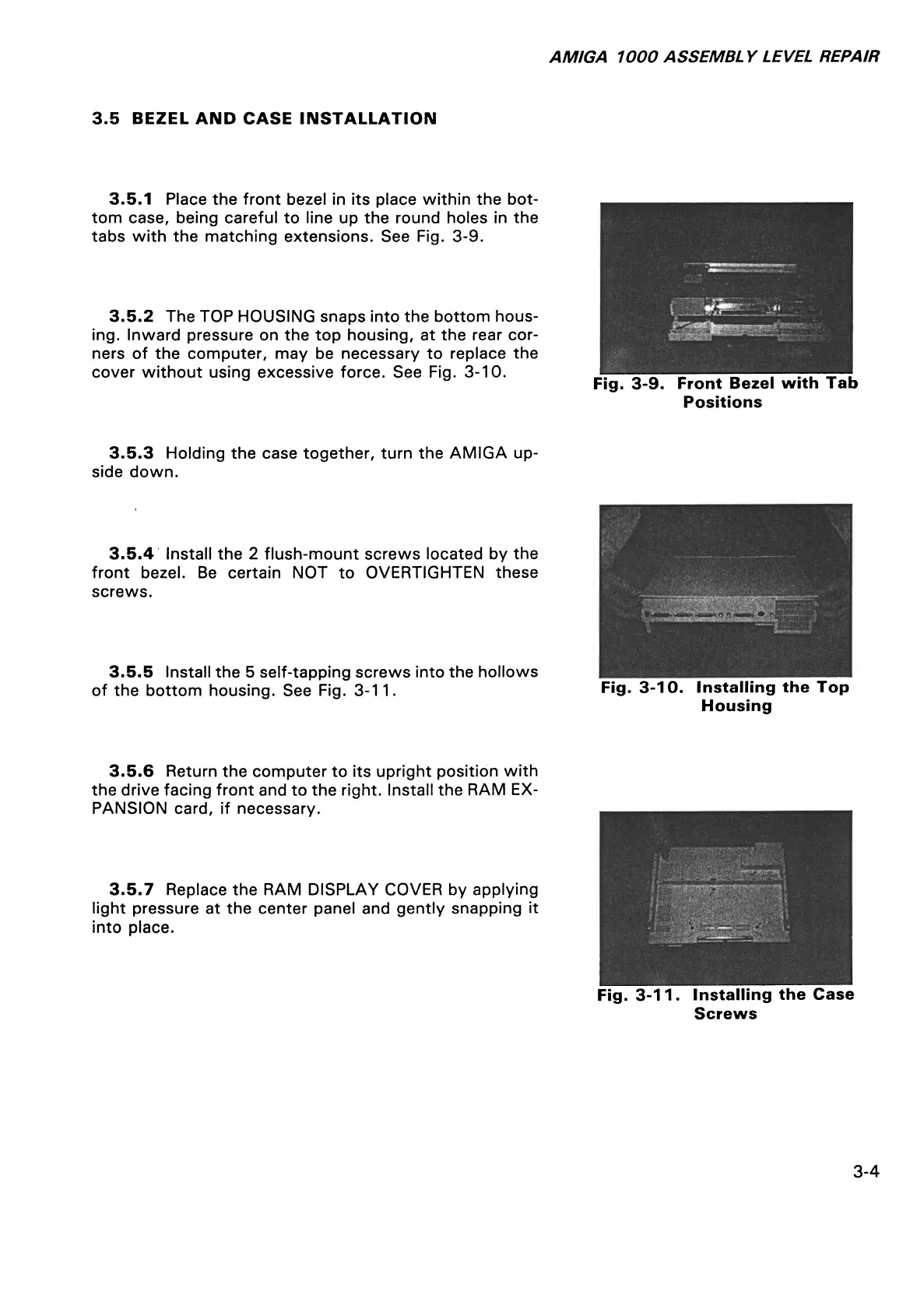
3.5.1 Place the front bezel in its place within the bot
tom case, being careful to line up the round holes in the
tabs with the matching extensions. See Fig. 3-9.
3.5.2 The TOP HOUSING snaps into the bottom hous
ing. Inward pressure on the top housing, at the rear cor
ners of the computer, may be necessary to replace the
cover without using excessive force. See Fig. 3-10.
Fig. 3-9. Front Bezel with Tab
Positions
3.5.3 Holding the case together, turn the AMIGA up
side down.
3.5.4 Install the 2 flush-mount screws located by the
front bezel. Be certain NOT to OVERTIGHTEN these
screws.
3.5.5 Install the 5 self-tapping screws into the hollows
of the bottom housing. See Fig. 3-11.
Fig. 3-10. Installing the Top
Housing
3.5.6 Return the computer to its upright position with
the drive facing front and to the right. Install the RAM EX
PANSION card, if necessary.
3.5.7 Replace the RAM DISPLAY COVER by applying
light pressure at the center panel and gently snapping it
into place.
Fig. 3-11. Installing the Case
Screws
3-4