AMIGA 1000 ASSEMBLY LEVEL REPAIR
3.4 INSTALLING THE TOP RFI SHIELD
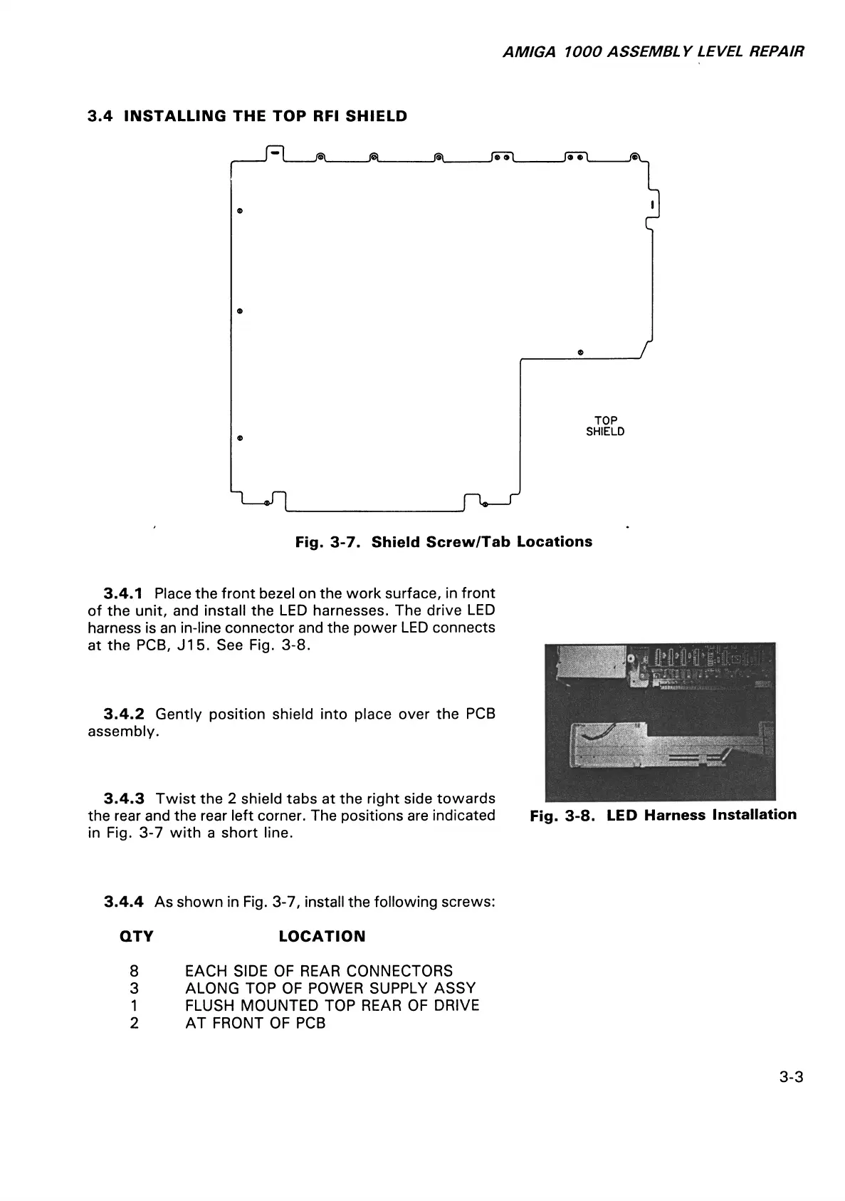
Fig. 3-7. Shield Screw/Tab Locations
3.4.1 Place the front bezel on the work surface, in front
of the unit, and install the LED harnesses. The drive LED
harness is an in-line connector and the power LED connects
at the PCB, J15. See Fig. 3-8.
3.4.2 Gently position shield into place over the PCB
assembly.
3.4.3 Twist the 2 shield tabs at the right side towards
the rear and the rear left corner. The positions are indicated Fig. 3-8. LED Harness Installation
in Fig. 3-7 with a short line.
3.4.4 As shown in Fig. 3-7, install the following screws:
QTY LOCATION
8 EACH SIDE OF REAR CONNECTORS
3 ALONG TOP OF POWER SUPPLY ASSY
1 FLUSH MOUNTED TOP REAR OF DRIVE
2 AT FRONT OF PCB
3-3