AMIGA 1000 ASSEMBLY LEVEL REPAIR
3.3 DRIVE INSTALLATION
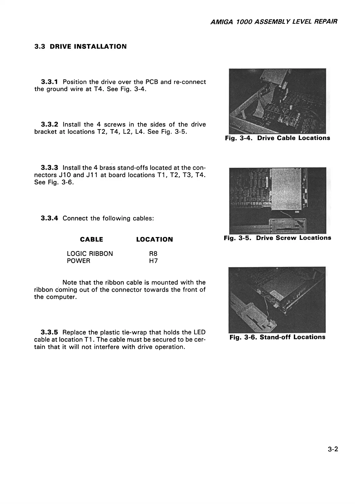
3.3.1 Position the drive over the PCB and re-connect
the ground wire at T4. See Fig. 3-4.
3.3.2 Install the 4 screws in the sides of the drive
bracket at locations T2, T4, L2, L4. See Fig. 3-5.
Fig. 3-4. Drive Cable Locations
3.3.3 Install the 4 brass stand-offs located at the con
nectors J10 and J11 at board locations T1, T2, T3, T4.
See Fig. 3-6.
3.3.4 Connect the following cables:
CABLE LOCATION
Fig. 3-5. Drive Screw Locations
LOGIC RIBBON R8
POWER H7
Note that the ribbon cable is mounted with the
ribbon coming out of the connector towards the front of
the computer.
3.3.5 Replace the plastic tie-wrap that holds the LED
cable at location T1. The cable must be secured to be cer
tain that it will not interfere with drive operation.
Fig. 3-6. Stand-off Locations
3-2