AMIGA 1000 ASSEMBLY LEVEL REPAIR
SECTION 3. AMIGA ASSEMBLY
3.1 POWER SUPPLY INSTALLATION
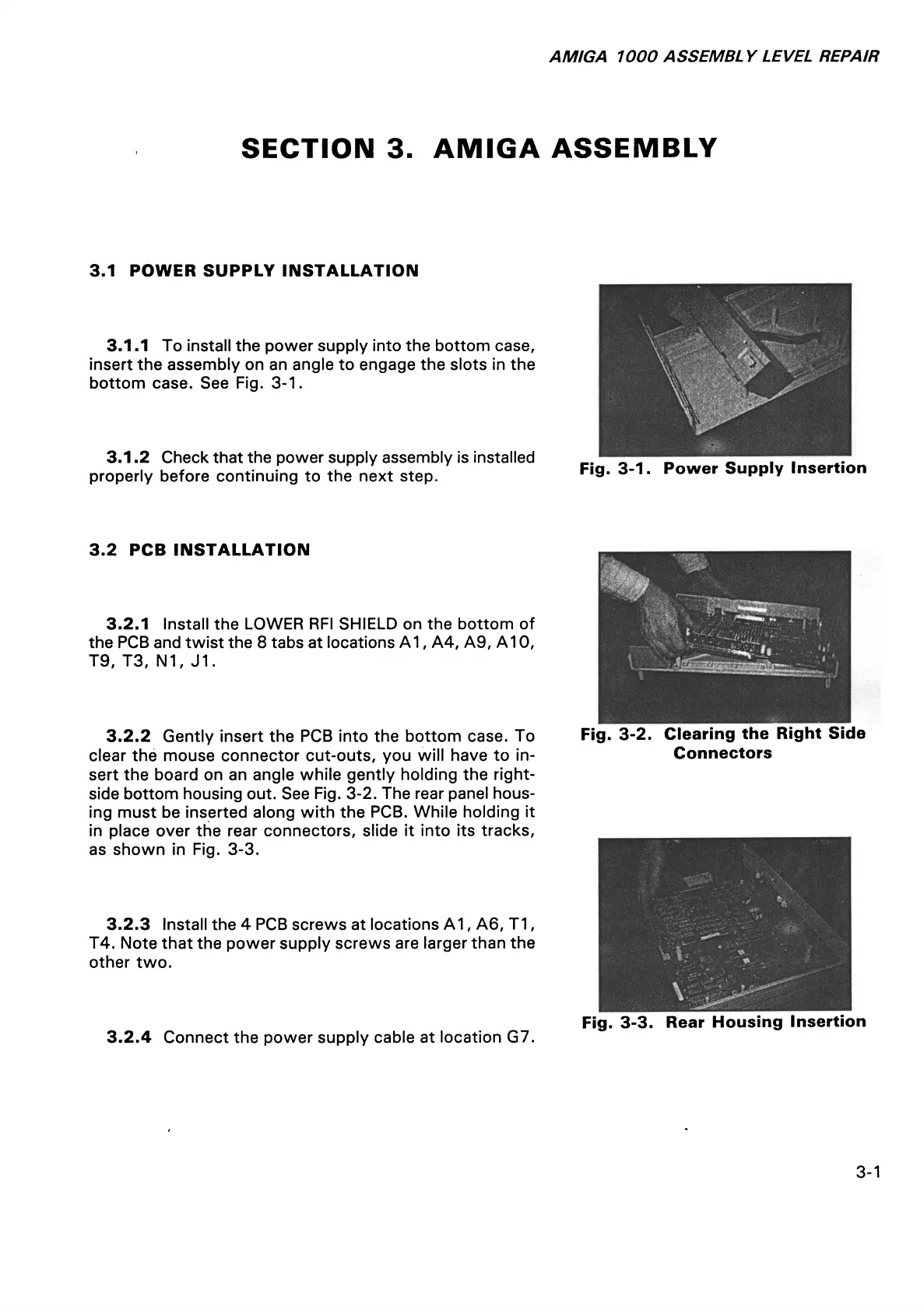
3.1.1 To install the power supply into the bottom case,
insert the assembly on an angle to engage the slots in the
bottom case. See Fig. 3-1.
3.1.2 Check that the power supply assembly is installed
properly before continuing to the next step.
Fig. 3-1. Power Supply Insertion
3.2 PCB INSTALLATION
3.2.1 Install the LOWER RFI SHIELD on the bottom of
the PCB and twist the 8 tabs at locations A1, A4, A9, A10,
T9, T3, N1, J1.
3.2.2 Gently insert the PCB into the bottom case. To
clear the mouse connector cut-outs, you will have to in
sert the board on an angle while gently holding the right-
side bottom housing out. See Fig. 3-2. The rear panel hous
ing must be inserted along with the PCB. While holding it
in place over the rear connectors, slide it into its tracks,
as shown in Fig. 3-3.
3.2.3 Install the 4 PCB screws at locations A1, A6, T1,
T4. Note that the power supply screws are larger than the
other two.
3.2.4 Connect the power supply cable at location G7.
Fig. 3-2. Clearing the Right Side
Connectors
Fig. 3-3. Rear Housing Insertion
3-1