AMIGA 1000 ASSEMBLY LEVEL REPAIR
2.6 PCB REMOVAL
CAUTION: Do NOT remove the 4
screws that secure the
card edge connector
shields at locations.
2.6.1 Disconnect the power supply cable at location
G7.
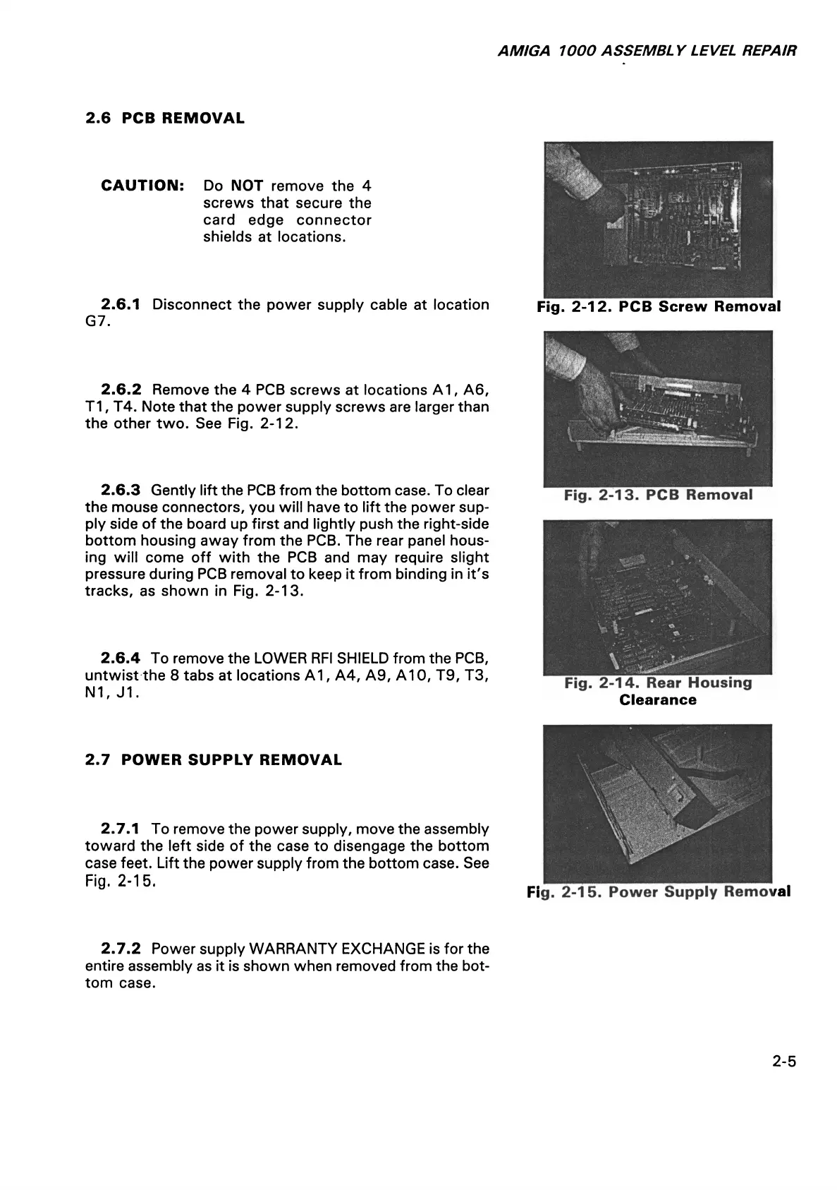
2.6.2 Remove the 4 PCB screws at locations A 1, A6,
T1, T4. Note that the power supply screws are larger than
the other two. See Fig. 2-12.
2.6.3 Gently lift the PCB from the bottom case. To clear
the mouse connectors, you will have to lift the power sup
ply side of the board up first and lightly push the right-side
bottom housing away from the PCB. The rear panel hous
ing will come off with the PCB and may require slight
pressure during PCB removal to keep it from binding in it's
tracks, as shown in Fig. 2-13.
2.6.4 To remove the LOWER RFI SHIELD from the PCB,
untwist the 8 tabs at locations A1, A4, A9, A10, T9, T3,
N1, J1.
2.7 POWER SUPPLY REMOVAL
2.7.1 To remove the power supply, move the assembly
toward the left side of the case to disengage the bottom
case feet. Lift the power supply from the bottom case. See
Fig. 2-15.
Fig. 2-12. PCB Screw Removal
Clearance
Fig. 2-15. Power Supply Removal
2.7.2 Power supply WARRANTY EXCHANGE is for the
entire assembly as it is shown when removed from the bot
tom case.
2-5