AMIGA 1000 ASSEMBLY LEVEL REPAIR
NOTE: The Printed Circuit Board (PCB) in
the AMIGA is mapped with letters
along the front edge of the PCB
and numbers up the left side. Map
locations for items described in the
text are listed as the intersections
of these points. An indication of
C2, for instance, indicates the
board area where a line, running
vertically from the 'C' marked on
the PCB edge and horizontally
across from the '2' printed on the
left of the PCB, intersects. The
map points in this text are
estimates of the PCB area in which
a connector or screw may be
found.
Fig. 2-9. internal View
2.5 DRIVE REMOVAL
2.5.1 Remove the 4 brass stand-offs located at the con
nectors J10 and J11 at board locations T1, T2, T3, T4.
See Fig. 2-10.
2.5.2 Remove the 4 screws from the sides of the drive
bracket at locations T2, T4, L2, L4.
2.5.3 Remove the following cables:
CABLE LOCATION
LOGIC RIBBON R8
POWER H7
Fig. 2-10. Stand-Off Locations
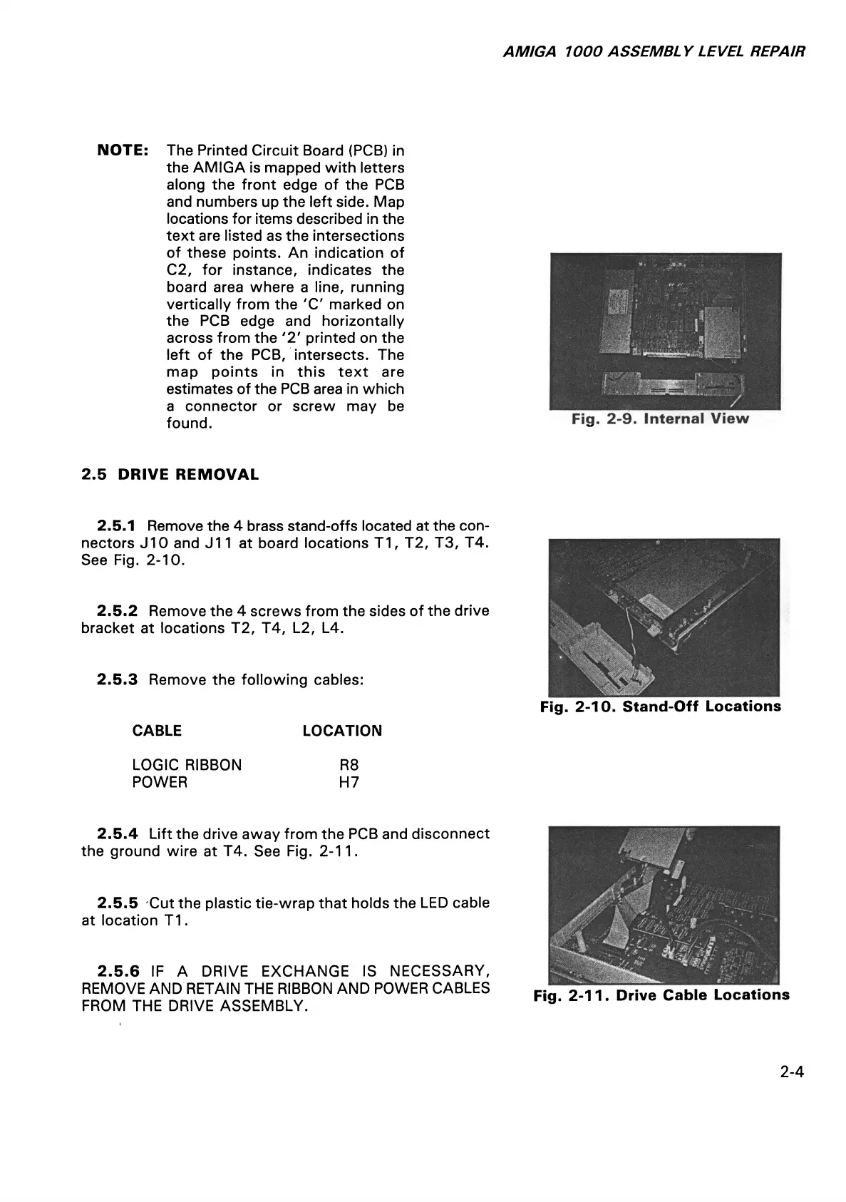
2.5.4 Lift the drive away from the PCB and disconnect
the ground wire at T4. See Fig. 2-11.
2.5.5 Cut the plastic tie-wrap that holds the LED cable
at location T1.
2 .5.6 IF A DRIVE EXCHANGE IS NECESSARY,
REMOVE AND RETAIN THE RIBBON AND POWER CABLES
FROM THE DRIVE ASSEMBLY.
Fig. 2-11. Drive Cable Locations
2-4