AMIGA 1000 ASSEMBLY LEVEL REPAIR
2.4 REMOVING THE TOP RFI SHIELD
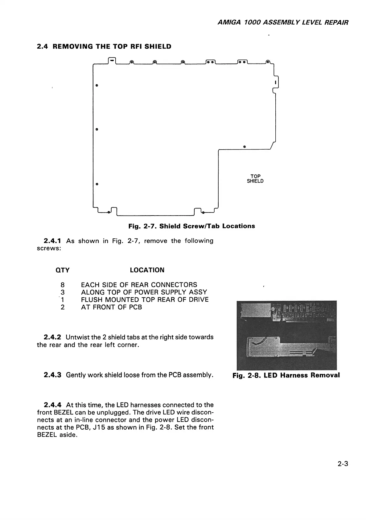
2.4.1 As shown in Fig. 2-7, remove the following
screws:
QTY LOCATION
8 EACH SIDE OF REAR CONNECTORS
3 ALONG TOP OF POWER SUPPLY ASSY
1 FLUSH MOUNTED TOP REAR OF DRIVE
2 AT FRONT OF PCB
2.4.2 Untwist the 2 shield tabs at the right side towards
the rear and the rear left corner.
2.4.3 Gently work shield loose from the PCB assembly. Fig. 2-8. LED Harness Removal
2.4.4 At this time, the LED harnesses connected to the
front BEZEL can be unplugged. The drive LED wire discon
nects at an in-line connector and the power LED discon
nects at the PCB, J15 as shown in Fig. 2-8. Set the front
BEZEL aside.
2-3