AMIGA 1000 ASSEMBLY LEVEL REPAIR
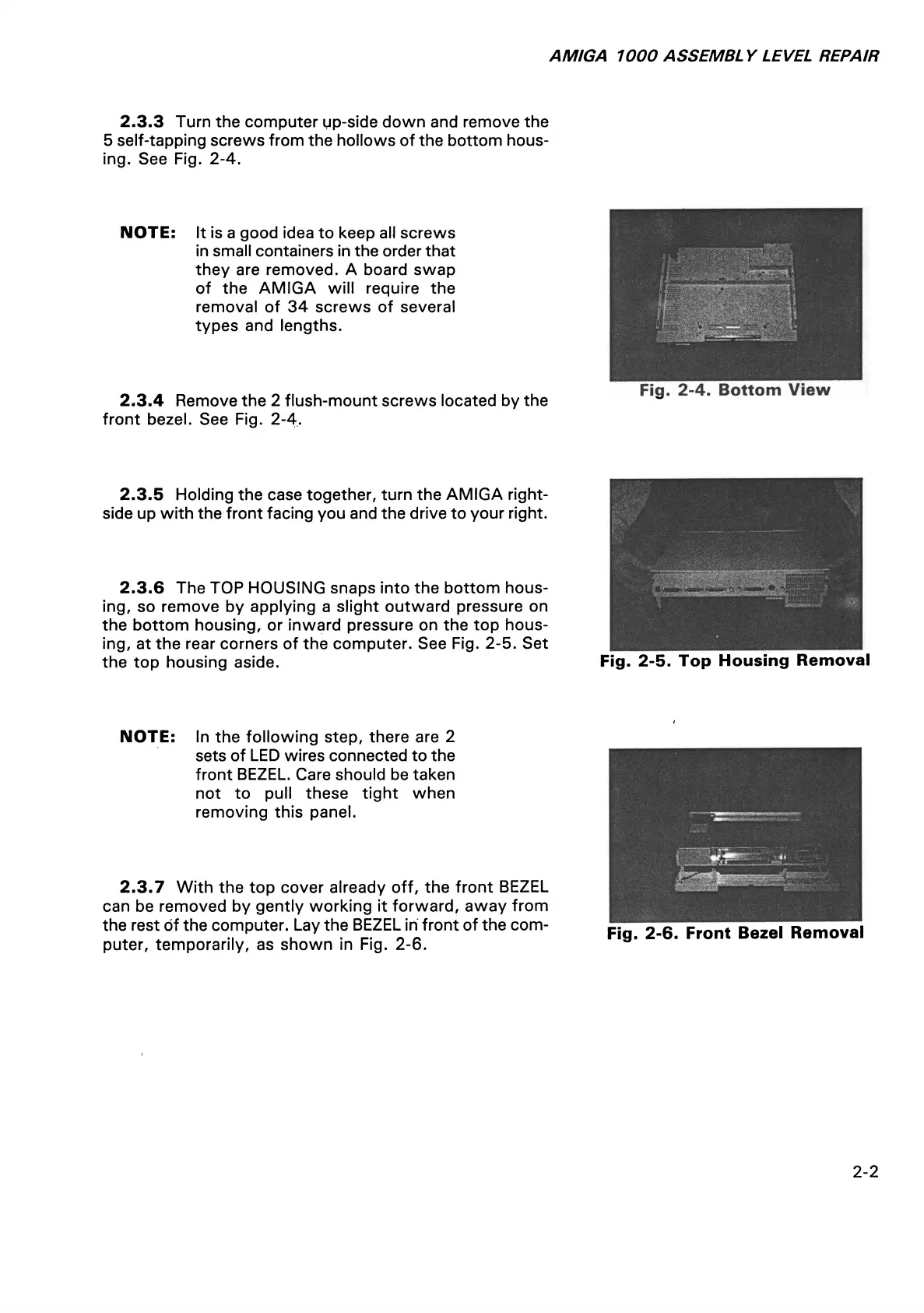
2.3.3 Turn the computer up-side down and remove the
5 self-tapping screws from the hollows of the bottom hous
ing. See Fig. 2-4.
NOTE: It is a good idea to keep all screws
in small containers in the order that
they are removed. A board swap
of the AMIGA will require the
removal of 34 screws of several
types and lengths.
2.3.4 Remove the 2 flush-mount screws located by the
front bezel. See Fig. 2-4.
Fig. 2-4. Bottom View
2.3.5 Holding the case together, turn the AMIGA right-
side up with the front facing you and the drive to your right.
2.3.6 The TOP HOUSING snaps into the bottom hous
ing, so remove by applying a slight outward pressure on
the bottom housing, or inward pressure on the top hous
ing, at the rear corners of the computer. See Fig. 2-5. Set
the top housing aside.
Fig. 2-5. Top Housing Removal
NOTE: In the following step, there are 2
sets of LED wires connected to the
front BEZEL. Care should be taken
not to pull these tight when
removing this panel.
2.3.7 With the top cover already off, the front BEZEL
can be removed by gently working it forward, away from
the rest of the computer. Lay the BEZEL in front of the com
puter, temporarily, as shown in Fig. 2-6.
Fig. 2-6. Front Bezel Removal
2-2