AMIGA 1000 ASSEMBLY LEVEL REPAIR
SECTION 2. COMPUTER DISASSEMBLY
PLEASE NOTE: The disassembly of the AMIGA 1000 should only be
attempted by a qualified technician using proper static
protection procedures and equipment.
2.1 REAR CONNECTORS
2.1.1 Set power switch to OFF position and remove
power cord.
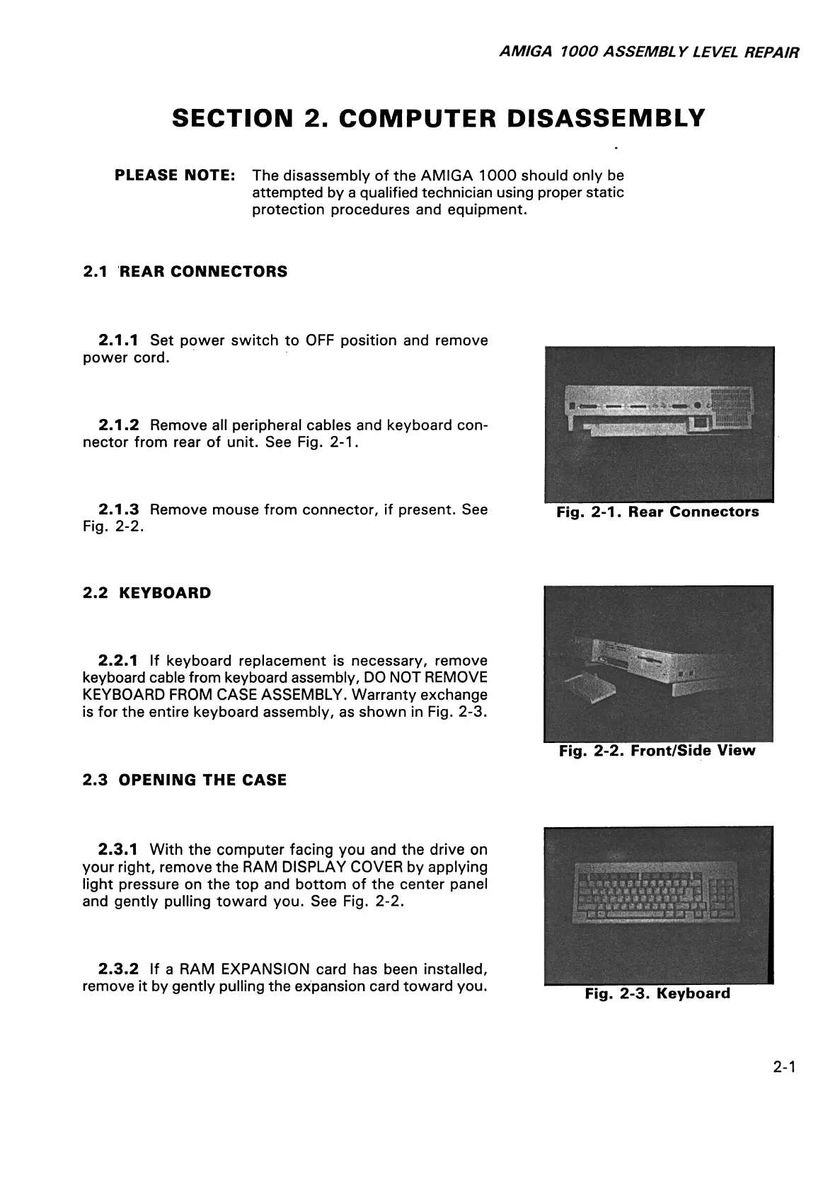
2.1.2 Remove all peripheral cables and keyboard con
nector from rear of unit. See Fig. 2-1.
2.1.3 Remove mouse from connector, if present. See
Fig. 2-2.
Fig. 2-1. Rear Connectors
2.2 KEYBOARD
2.2.1 If keyboard replacement is necessary, remove
keyboard cable from keyboard assembly, DO NOT REMOVE
KEYBOARD FROM CASE ASSEMBLY. Warranty exchange
is for the entire keyboard assembly, as shown in Fig. 2-3.
Fig. 2-2. Front/Side View
2.3 OPENING THE CASE
2.3.1 With the computer facing you and the drive on
your right, remove the RAM DISPLAY COVER by applying
light pressure on the top and bottom of the center panel
and gently pulling toward you. See Fig. 2-2.
2.3.2 If a RAM EXPANSION card has been installed,
remove it by gently pulling the expansion card toward you.
i m a s m & & e ■ m. m
I ■ a i * i a t t a i n a * $
9
a
% i t % 9 * m $ a m m m I
mm # # * 4 is a n ^
t% mi- a mmmr
■
Fig. 2-3. Keyboard
2-1