D SERIES Ceiling Loudspeakers Installation and Operation Manual Page 11
Back Can Installation
General
Lay out the loudspeaker locations according to the requirements of the specific
installation and in compliance with applicable safety and building codes. It is
beyond the scope of this manual to provide guidance in this area. Community
does, however, oer our Forecaster HD ceiling system software to assist you
in distributed loudspeaker system design. Please visit the Products/Software
page of the Community website for this software.
We also encourage you to use the provided seismic safety tabs to secure the
back cans to the building structure. Again, please be guided by applicable
building codes here; we cannot provide detailed rigging instructions due to the
wide global variations in such codes and practices.
Procedure (for suspended ceiling)
Note: The optimum situation for installation is into a ceiling where the suspension grid
is installed and the tiles have not yet been placed. We designed this series to facilitate
installation into an already-placed ceiling, and we are writing the instructions to
conform to this more restrictive condition. So when we say something like, "pass the tile
bridge support rails through the can cutout," and the adjacent space is unobstructed, of
course you should feel free to use the more sensible alternative and just drop the rails
into place.
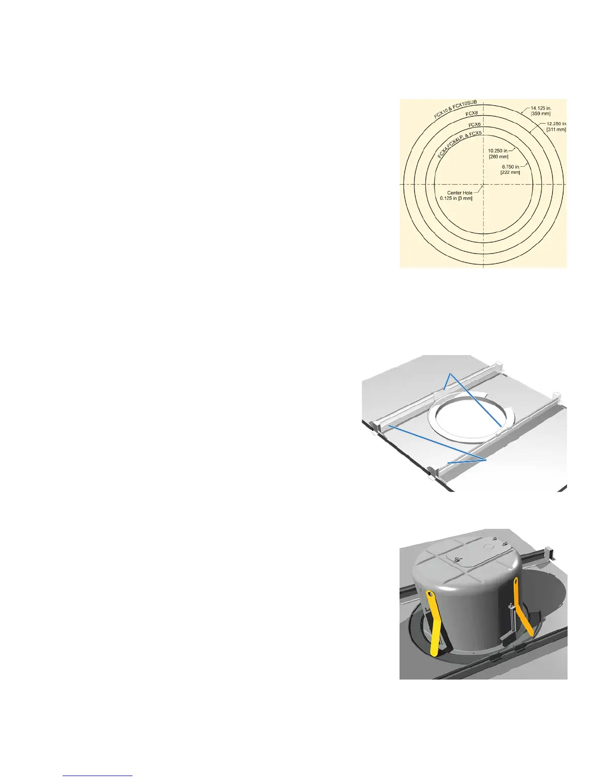
1. Mark the hole location on the ceiling tiles and, using the cutout template
provided with your D SERIES loudspeakers, cut a hole to the precise size
(Figure 7).
2. Insert the bridge support rails through the can cutout and position
them across the rails on either side of the cutout, approximately as
far apart as the clips on the C-ring support plate. See Figure 8.
Notes: The bridge support rails each have a raised rib with a flat stabilizing
flange on one side which keeps the rail from tipping toward the loudspeaker it is
supporting. For this reason, be sure to place the rails so that these stabilizing
flanges are facing inward toward the cutout.
Community oers 48" (1219mm) tile rails (D-RAIL48-PR) for applications
utilizing larger 4 foot long tiles. Install them in the same way as the 24" rails
shown at right.
3. Guide the C-ring support plate through the cutout hole and position
it centered in the hole and aligned so its attachment clips are closest
to the tile bridges you just placed. Slide these bridges as necessary
so the C-ring clips can be pressed onto the raised rail ribs, and now
snap the C-ring clips onto the rails (Figure 8).
4. Slide the back can into the hole, aligning it so that its input terminal
block OR its knockout strain relief locations are consistent with the
wiring distribution you have mapped out. When you press the can
fully into place, the four spring-loaded Drop-Stop™ tabs will spread
atop the C-ring, and you may hear them "snap" into position; you
can now continue without having to hold the can in place (Figure 9).
Figure 8. Installing a C-ring support plate onto tile
bridge support rails
Stabilizing
flanges
Attachment Clips
Figure 7. Cutout template dimensions
Figure 9. Highlighted Drop-Stop™ tabs
snap out over C-ring support
(Temporarily holds can in place even
before you secure it with the steel
mounting clamps)