Page 6 Installation and Operation Manual D SERIES Ceiling Loudspeakers
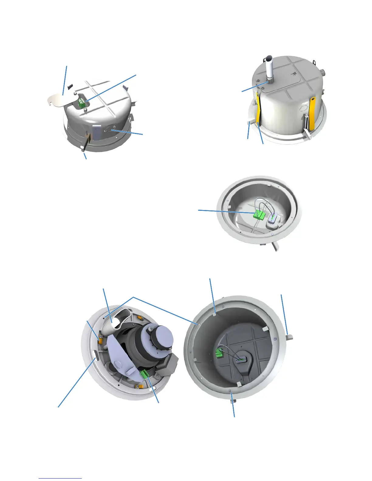
Component Identification
Internal leads and plug to bring rear terminal block signal
to the loudspeaker’s input connector on the circuit board
Figure 1. Component part identification (1 of 2)
Twist-Assist™ can
mating clip (4 typical)
Zinc plated steel can-
locking clamp (4 typical)
Dog screw alignment slot
(4 typical). Used to align face in
proper location when installing
back can
Bass reflex port
Hole for 4mm sheet metal
screw (4 typical)
Loudspeaker input
connector on circuit board
Phillips-head can-locking clamp
actuator (4 typical)
Twist-Assist™
face mounting clip
(4 typical)
Combination terminal block cover and cable strain
relief clamp
Input terminal block
3/4" and 1" knockout
strain relief
Knockout strain relief on terminal
block cover (with conduit installed)
Steel can-locking clamp
(shown deployed)
Zinc plated steel can-
locking clamp (4 typical)
Drop-Stop™ tab
(4 typical)