2
Chapter2 System installation
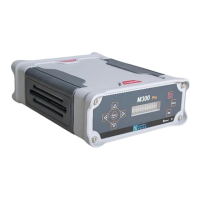
2.1 Front panel introduction
Front panel of M300 receiver
Ref. # Description
❶ 3 LED indicates the work status of the receiver.
PWR: power indicator. After power on, this LED will light in red colour
SAT: satellites indicator. It will flash several times every 5 seconds, which means how many
satellites locked by the receiver.
LINK: correction message. As a base station, flash once per second means sending correction
message 1/s; as a rover, it means receiving correction message. In the raw data recording mode
(data recorded in the memory of receiver), this LED will also flash according to sampling interval.
❷ TNC GNSS antenna connector
❸ TNC UHF antenna connector
❹ DC1: serial port communication with Com 1 of OEM Board. Appendix A: the Pin definition
of this port.
❺ DC3: serial port communication with internal UHF and Com 3 of OEM card.
2.2 Antenna installation
The Installation of GNSS antenna is a very important factor affecting the performance of
receivers. It will have a great influence on the visibility of satellites and SNR, so the antenna
should be in open area and far away from big power electromagnetic radiation devices.