COMPA TECH S.r.l.
Web: www.compasaw.com - E-mail: info@compasaw.com
Tel. (+39) 059 527887 - Fax (+39) 059527889
- 30 -
ENGLISH
Operator’s handbook
The inclination is obtained as follows:
unlock spring lever M (fi g. 13) located on the
back of the machine.
tilt the saw-motor arm using the handle to the
desired angle which you can read on the ruler
printed near the hinge point of the rotation
(fi g.14), once you have reached the desired
angle lock lever M.
While cutting it is advisable to hold the
handle tightly and keep the piece being
processed well locked on the work base
and against the support edge (fi g. 15).
5.6.4 Mounting and replacing the blade
ATTENTION! Wear work gloves for this
operation and only start after removing the
plug from the socket (fi g.7).
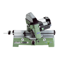
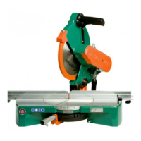
Mod. JET
Raise the upper surface to its maximum
height (see point 6.3).
Mounting and/or replacement of the blade is done
as follows:
if the arm is locked in the lowered position, unlock
it by pulling knob N (fi g. 16) out and bringing the
arm to its raised standby position.
pull in and at the same time pull up lever O (fi g.
17) in order to rotate inner guard P (fi g.18) insi-
de the sawmotor arm to its limit.
lock the motor shaft by inserting a 6mm Allen
spanner Q (fi g. 19) in the central hole of the
motor fan cover and unscrew the left screw with
the 8 mm Allen spanner R (both spanners are
supplied).
completely unscrew and remove the screw, then
remove the external fl ange.
ATTENTION: use work gloves to handle
materials and cutting tools.
ATTENTION: do not mount damaged bla-
des. Only use cutting tools in conformity
with EN 847-1.
5.7 Type of service of the machine
The machine is designed for non continuous operation;
see the Service Type in the technical specifi cations and
only use the machine in the way described.
The work cycle should consist of a period of operation
and a cool down period. The aim is to prevent the mo-
tor from overheating or developing faults.
Example: with a service “S3-50%” the work period of
the machine should be followed by a cool-down period
of equal time, in order to allow the machine to cool
to its initial temperature. The cool-down period varies
according to the ambient temperature and wind condi-
tions (fi g. 43).