9
This manual includes installation, operating
instructions and maintenance and service
procedures for the Model 15, 20, 25, and 30
SS and CUB air compressor units.
An explanation of the model code follows:
Example: CL20 CUB
CL-CompAir LeROI
20 - Horsepower required to drive the air end
CUB - Modulation control
This series of air compressor units are
electric motor driven, oil flooded, single stage,
rotary screw type.
These compressors are air cooled with the oil
cooler and aftercooler mounted as an
assembly.
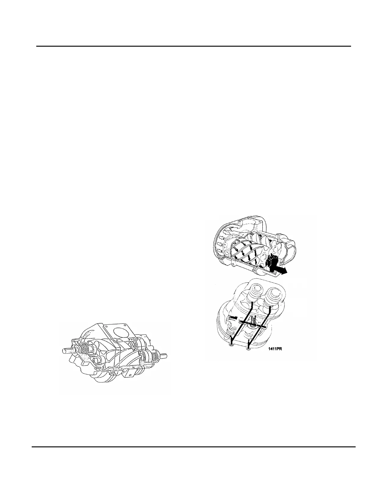
AIR END (Figure 1)
The air end (male rotor) is belt driven. The
female rotor is driven by the male rotor
because the rotors are meshed. Figure 2
shows the direction of rotor rotation and the
air/oil flow through the air end. Note that the
air flow through the air end is between the
rotors and the inside diameter of the cylinder
bore.
FIGURE 1 - AIR END
Each rotor is mounted with two angular
contact ball bearings at the rear or discharge
end. The front or inlet end of each rotor is
supported by a single row roller bearing. This
allows the rotors or cylinder to freely expand
or contract due to changes in temperature
without affecting critical running clearances.
AIR AND OIL FLOW
Air circulates through the system beginning
at the air cleaner, passing through the intake
valve and into the air end where it is
compressed. During compression oil is
injected into the air end (and air) to provide
cooling, sealing and lubrication. From the air
end compressed air (and oil) is discharged at
rated pressure into the unit air receiver/oil
reservoir.
FIGURE 2 - AIR/OIL FLOW - TYPICAL
Separation of oil from the air, which was
injected into the air end during compression,
begins in the unit air receiver/oil reservoir.
From 90 to 95% of the oil is separated from
the air with a decrease in air velocity,
changes in flow direction, adequate baffling
and proper location of the air receiver/oil
reservoir inlet port.
SECTION I
GENERAL INFORMATION