29
CONTROLS
Adjustment to all controls are made very
carefully at the factory. However, it may be
necessary to make certain adjustments at
the time the unit is installed, to fit specific
applications, or after repair or replacement of
components.
The control pressure regulator valve (CPR) is
the only control device which may require
adjustment.
CAUTION
DO NOT EXCEED THE RATED MAXIMUM
FULLY LOAD OPERATING PRESSURE OF
ANY UNIT. REFER TO “SPECIFICATIONS”,
SECTION II.
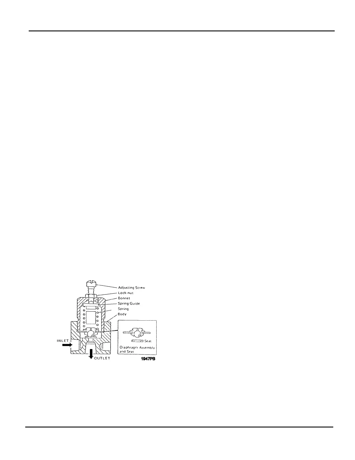
MODULATING CONTROL - CONTROL
PRESSURE REGULATOR (CPR) VALVE
ADJUSTMENT (Figure 11)
To change the pressure at which the CPR
(control pressure regulator) valve will fully
unload the compressor, loosen the adjusting
screw locknut and turn the adjusting screw in
(clockwise) to increase of out
(counterclockwise) to decrease pressure.
Tighten the locknut securely when finished.
FIGURE 11 - CONTROL PRESSURE
REGULATOR VALVE
Follow this procedure:
1. Install/connect pressure test gages
(minimum pressure range 200 psi), if
required, in place of the existing air
pressure gages.
2. Connect a pressure test gage with a
minimum range of 100 psi in the control
pressure line near the air intake valve.
WARNING
AIR ESCAPING TO ATMOSPHERE IS
NOISY. WEAR EAR PROTECTION TO
PROTECT HEARING AGAINST HIGH
INTENSITY NOISE.
3. Open the drop leg or receiver vent valve.
Start the unit. Slowly close the drop leg
or vent valve to raise both the unit and
system receiver air pressure to 80 psi,
approximately. Allow the unit to run long
enough to reach normal operating
temperature.
4. Adjust the service (drop leg or vent)
valve to maintain a constant rated full
load pressure. (i.e. 100, 125 or 150 psi).
CAUTION
CHECK SECTION II OF THIS MANUAL TO
OBTAIN INFORMATION ABOUT
MAXIMUM OPERATING PRESSURE AND
AIR END SPEED.
5. Observe the pressure test gage
connected in the control pressure line.
Loosen the adjusting screw locknut and
adjust the control pressure regulator
(CPR) valve by turning the adjusting
screw out (counterclockwise) until a
pressure of 3 to 5 psi is observed on the
control line test gage.
6. Then turn the CPR valve adjusting
screw in (clockwise) far enough to obtain
a control pressure of zero. (No control
air bleed). Securely tighten adjusting
screw locknut.
7. Cycle the controls by adjusting the
service (drop leg or vent) valve to raise
the lower both unit and system receiver
air pressure.
SECTION VI
CONTROLS AND ADJUSTMENT PROCEDURES