9. Service and maintenance
38
Procedure for changing the LC unit
a) Disconnect plug from lubrication system.
b) Unscrew lubricator (LC unit with drive and cover)
from the lubrication point.
c) Unscrew drive cover.
d) Remove drive from LC unit.
e) Check setting of decode switches (see Settings
section). (The decode switches are preset and
locked in the factory. They must not be changed.)
f) Place drive on new LC unit until the gears mesh.
Only use completely filled genuine CompAir LC
units.
g) Screw down drive cover to LC unit (hand tight).
h) Remove seal plug from LC unit.
i) Screw lubricators into lubrication point (hand tight).
j) Reconnect plug in drive.
k) After a reset, the lubrication system starts the
applicable pause time.
l) Check function: A green LED indicates a continuous
signal if the screw air compressor unitʼs drive motor
is running.
m) The lubricant in one LC unit MLS 120 is sufficient for
approx. 4000 Oh (only applies to the screw air
compressor range D110H RS) (this figure doesnʼt
include compressor downtimes).
9.2.4 Function display on lubricator
The LEDs for the function display are located on the
control plate and can be viewed through the transparent
cover.
The function display is only active if the screw air
compressor unitʼs drive motor is running.
The lubricators are fitted with one red and one green
LED. These LEDs signal the following operating modes
or faults to the operator.
1) When the lubricator issues this signal, the following
message is output on the compressor control:
[Warning: Mot.lubr. sys] (also refer to the operating
instructions for the compressor control DELCOS XL).
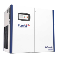
Settings available on the control plate
There are two decode switches on the control plate.
The protruding switches inscribed with “TIME” are for
setting the dispensing volume and the recessed
switches inscribed with “VOL” are for setting the size of
the LC unit.
Fig. 19 a
1 Function display (LED)
2 Protruding “TIME” switches
3 Recessed “VOL” switches
4 Plug connection
5 Plate
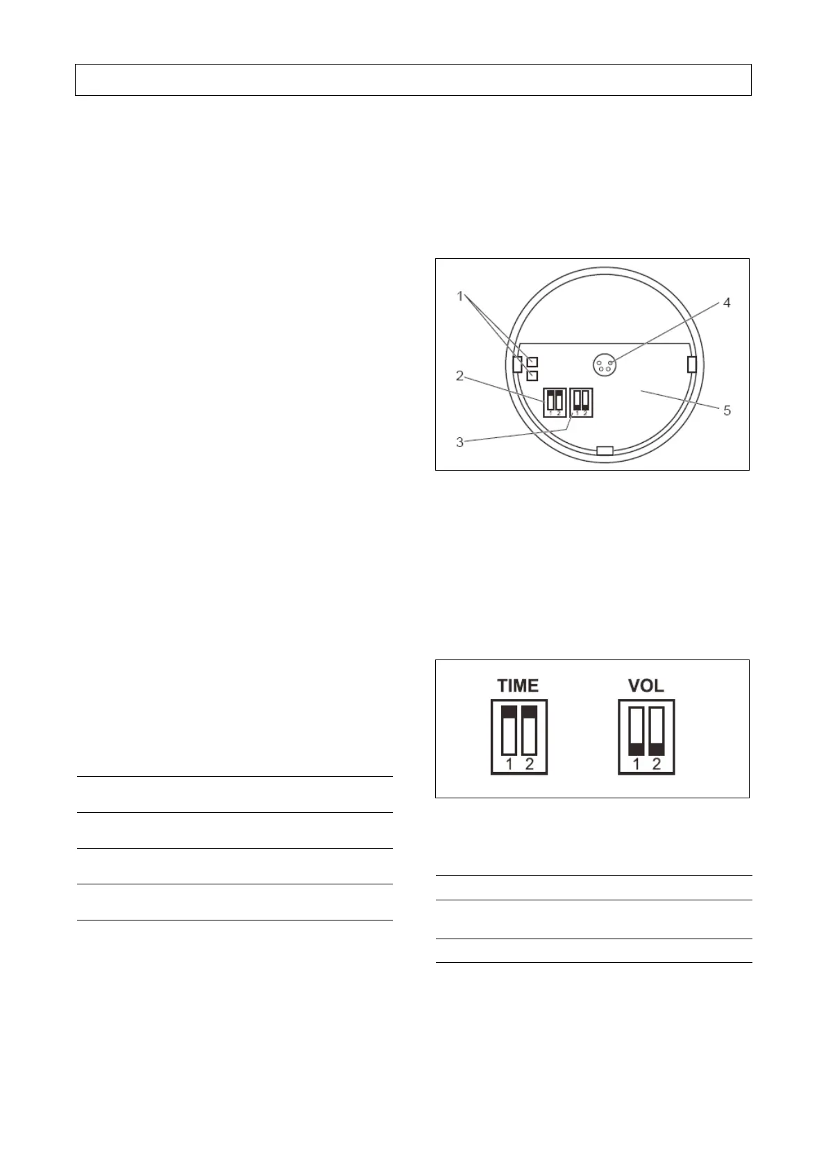
The following setting applies to the screw air
compressor range D110H RS / 50Hz + 60 Hz with a
standard electric motor:
Fig. 19 b)
 Loading...