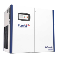
Fig. 31
Danger
Only perform checks and carry out work on the
screw compressor when the unit is out of
operation, depressurized, and secured from being
switched on again!
Caution when draining hot water: risk of scalding!
Allow the unit to cool down first.
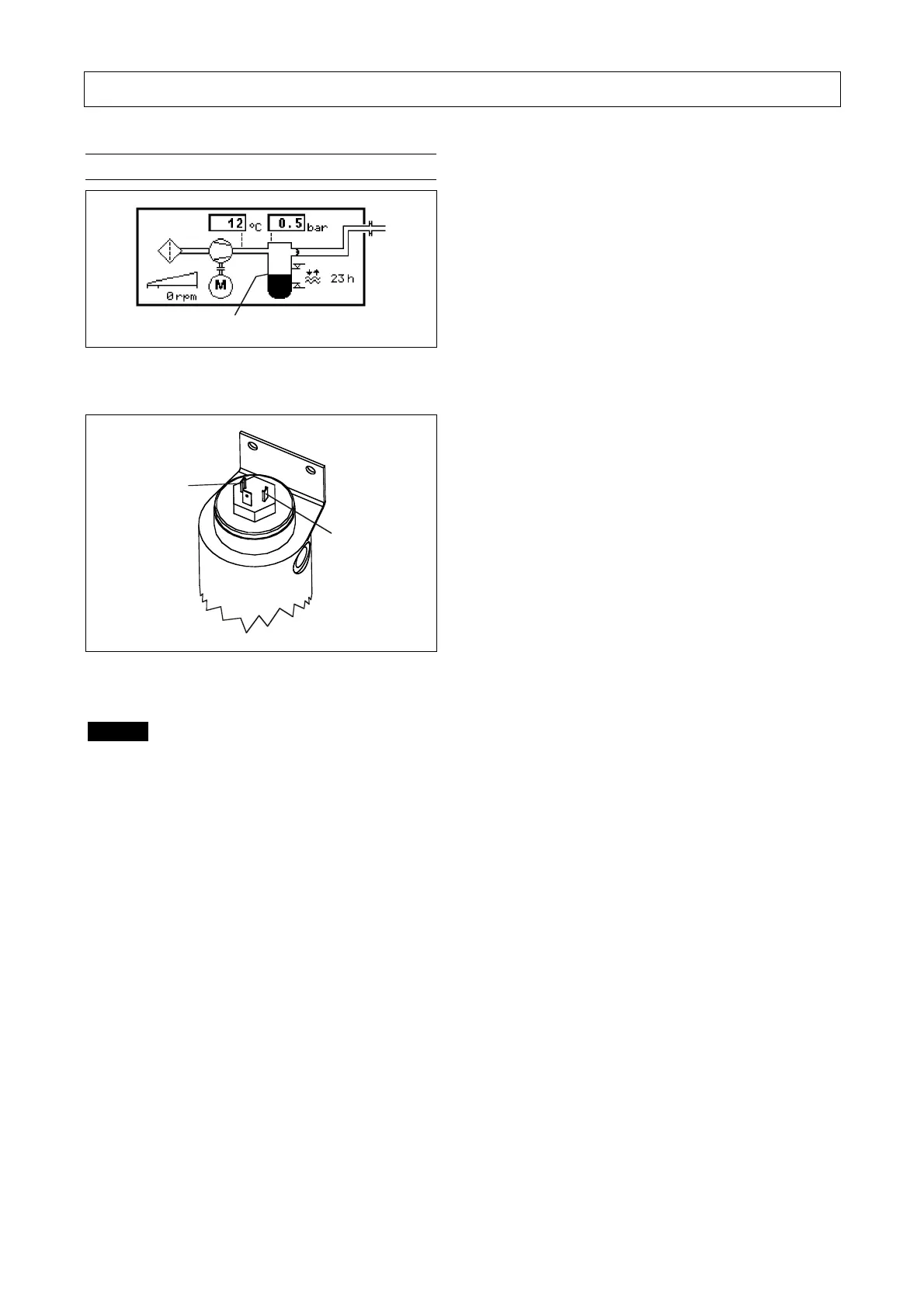
Check if the water level indicator on the DELCOS XL
display deviates greatly from the water level indicator
(-1- Fig. 30) on the pressure vessel.
If this is the case, or the DELCOS XL reports an error
with the water level sensor, then this should be checked
when the system is shut down as follows:
Raise the water level to approx. 50mm above the
'upper' mark of the water display indicator (-5- Fig. 16)
of the pressure vessel. The resistance value of both the
sensor connections (-1- and -2- Fig. 31) must lie
between 1376Ω and 1394Ω.
To check the lower sensor value, release the
connecting line from the lower screw connection of the
water level sensor. Drain the water level sensor into a
container provided. The drained water level sensor
must have a resistance at both the connections
(-1- and -2- Fig. 31) of between 990Ω and 1010Ω.
If one of these limit values is not reached, then the
water level sensor will have to be replaced.
After the checking and possible replacement of the
water level sensor, adjust the water level in the
pressure vessel again so that it is situated between
both the fill level marks (-4- and -5- Fig. 16) once more.