4. Design and functioning
25
Automatic operation (open-close operation)
• When the pressure reaches the upper switching
point set on the network pressure sensor (-7 - Fig.
5a), solenoid valve (Y1 Fig. 5a) is de-energised.
• The intake regulator (- 2 - Fig. 5a) is vented and
closed.
• The pressure reservoir (- 5 - Fig. 5a) is
depressurised via the intake filter.
• The compressor is now running in idle mode.
• If the mains pressure does not fall within 90
seconds (adjustable) to the lower switching point,
the system shuts down.
• If the lower switching point is reached in less than
90 seconds, the solenoid valve (- Y1 - Fig. 5a) is
energised again.
• The unit now changes over to on-load operation.
Stopping the system
• After pressing the OFF button
(Fig. 16) on the
operating panel, the solenoid valve (- Y1 - Fig. 5a)
is de-energised.
• The intake regulator (-2- Fig. 5a) closes and the
tank (-5- Fig. 5a) is relieved.
• After 30 seconds, the drive motor (- 3 - Fig. 5a) is
shut down.
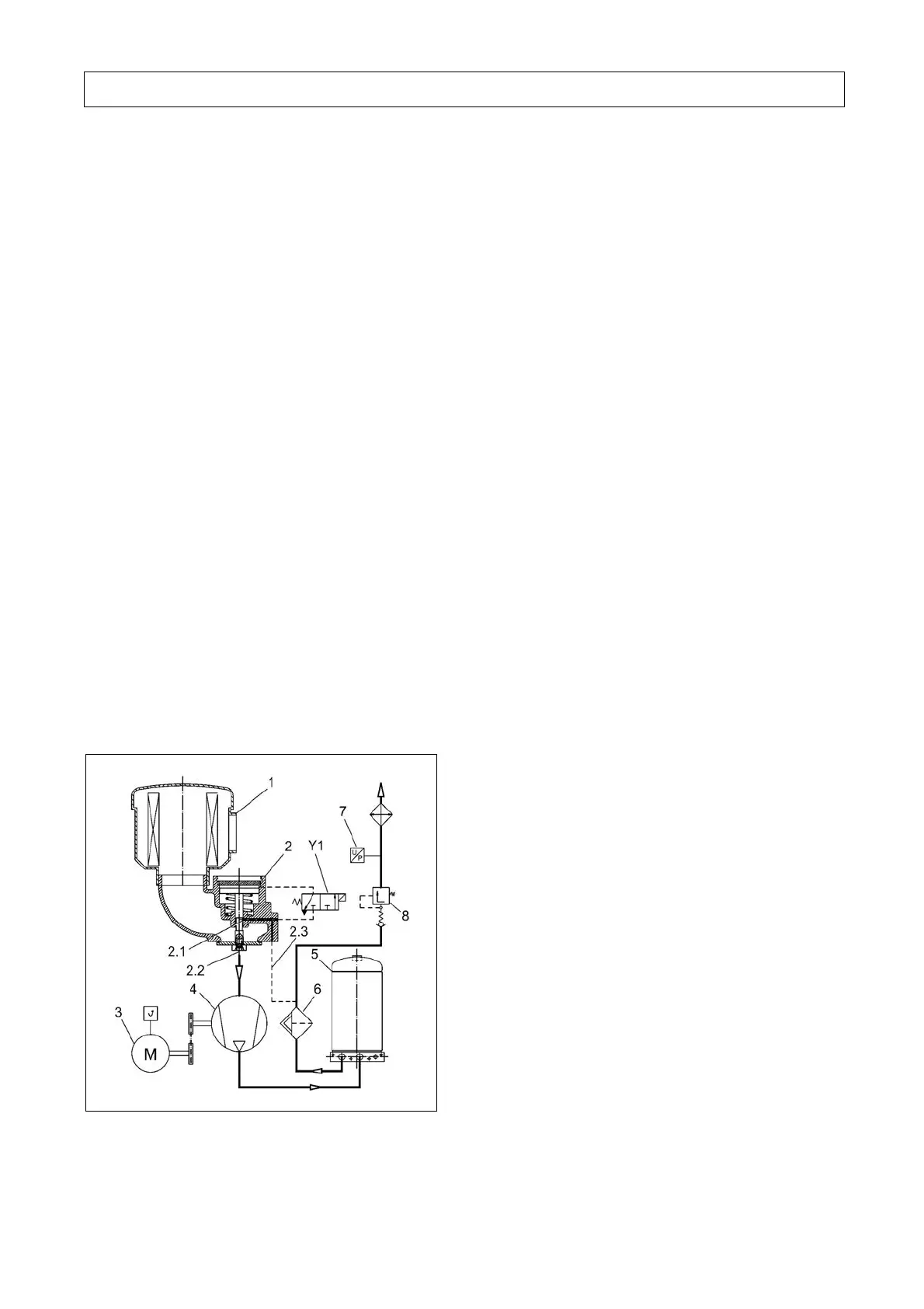
4.5.2 System control L15-L22
Fig. 5b L15-L22
Standstill of the system
• When the system is at rest the intake regulator
(- 2 - Fig. 5b) is closed.
• The solenoid valve (Y1 Fig. 5b) is de-energised.
• The pressure reservoir (- 6 - Fig. 5b) is bled via the
blow-off line (- 2.1- and -2.3- Fig. 5b) into the
suction channel.
Starting the system
• The motor (- 3 - Fig. 5b) starts up in the Y-mode.
• The compressor extracts a certain volume of air via
a start valve (- 2.2 - Fig. 5b). Pressure builds up in
the reservoir.
• When changing over to Δ-operation, the solenoid
valve (- Y1 - Fig. 5b) is energised and a connection
is then established between the pressure reservoir
and the intake regulator.
• The intake regulator opens.
• The minimum pressure valve (- 8 - Fig. 5b) opens
when the pressure reservoir is approx. 4.5 bar.
• Compressed air is now delivered into the consumer
network.
Automatic operation (open-close operation)
• When the pressure reaches the upper switching point
set on the network pressure sensor (-28 -(B1)),
solenoid valves (- 19 -(Y1) and - 20 - (Y4)) are de-
energised.
• The intake regulator (- 2 - Fig. 5b) is bled and closed.
• The pressure reservoir (- 5 - Fig. 5b) is
depressurised via the intake filter.
• The compressor is now running in idle mode.
• If the mains pressure does not fall within
90 seconds (adjustable) to the lower switching point,
the system shuts down.
• If the lower switching point is reached in less than
90 seconds, the solenoid valve (- Y1 - Fig. 5b) is
energised again.
• The unit now changes over to on-load operation.
Stopping the system
• After pressing the OFF button
(Fig. 16) on the
operating panel, the solenoid valve (- Y1 - Fig. 5b)
is de-energised.
• The intake regulator (-2- Fig. 5b) closes and the
tank (-5- Fig. 5b) is relieved.
After 30 seconds, the drive motor (- 3 - Fig. 5b) is shut
down.

 Loading...

