Under unfavourable local conditions, we recommend
the installation of venting ducts. However, the velocity
of the cooling air should not exceed 5 m/s. We
recommend a minimum duct cross-section of approx.
0.15 m
2
for L07-L11, 0.2 m
2
for L15-L22.
Important
The stated minimum cross-section refers to a
maximum duct length of 5 m/16.4 ft and a maximum
of one bend. In the event of differing values (over
5 m/16.4 ft, more than one bend, filter cartridges,
screens, etc.), please contact your technical
adviser.
CompAir screw compressors are rated for ambient
temperatures and cooling temperatures of +1°C/
33.8°F to +45°C/113°F. In the case of temperatures
other than the above limiting values, please consult
your technical adviser.
Note
In order to ensure a good heat dissipation, auxiliary
fans should be rated to process approximately 15 to
20% more air volume than the total cooling air
quantity required by the compressors installed in the
compressed air station.
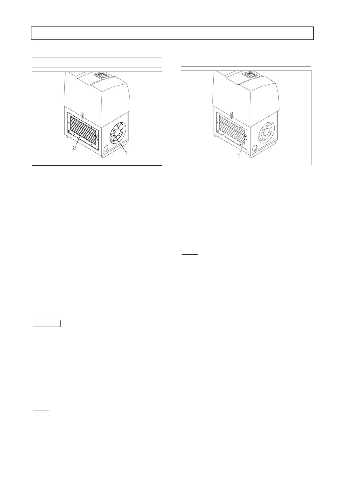
6.2 Compressed air connection
Fig. 10
1 Compressed air connection
The compressed air line system is connected at the
compressed air supply of the screw compressor
( - 1 - Fig. 10).
For this you should use a flexible connection
(e.g. compressed air hose, compensator).
L07-L11 sleeve G 3/4"
L15-L22 sleeve G 1"
Note
After-coolers, separators, collecting reservoirs and the
compressed air lines must be equipped with drain
facilities at their lowest points to drain collected liquids.
These facilities have to be fitted to allow the observance
of the draining of such liquids.
Hand-operated drain facilities have to be actuated in
accordance with the operating instructions.
Automatic drain facilities have to be checked for proper
function at regular intervals. When draining
condensates into a collecting line, which also collects
the condensate from other machines, make sure that
the collecting line is free from back pressure at all lines.
Condensate may contain oil! When draining
condensate, observe the corresponding regulations for
waste water disposal.

 Loading...

