installed (Section 5.3).
2. Remove the memory expansion board, if installed (Section 5.6).
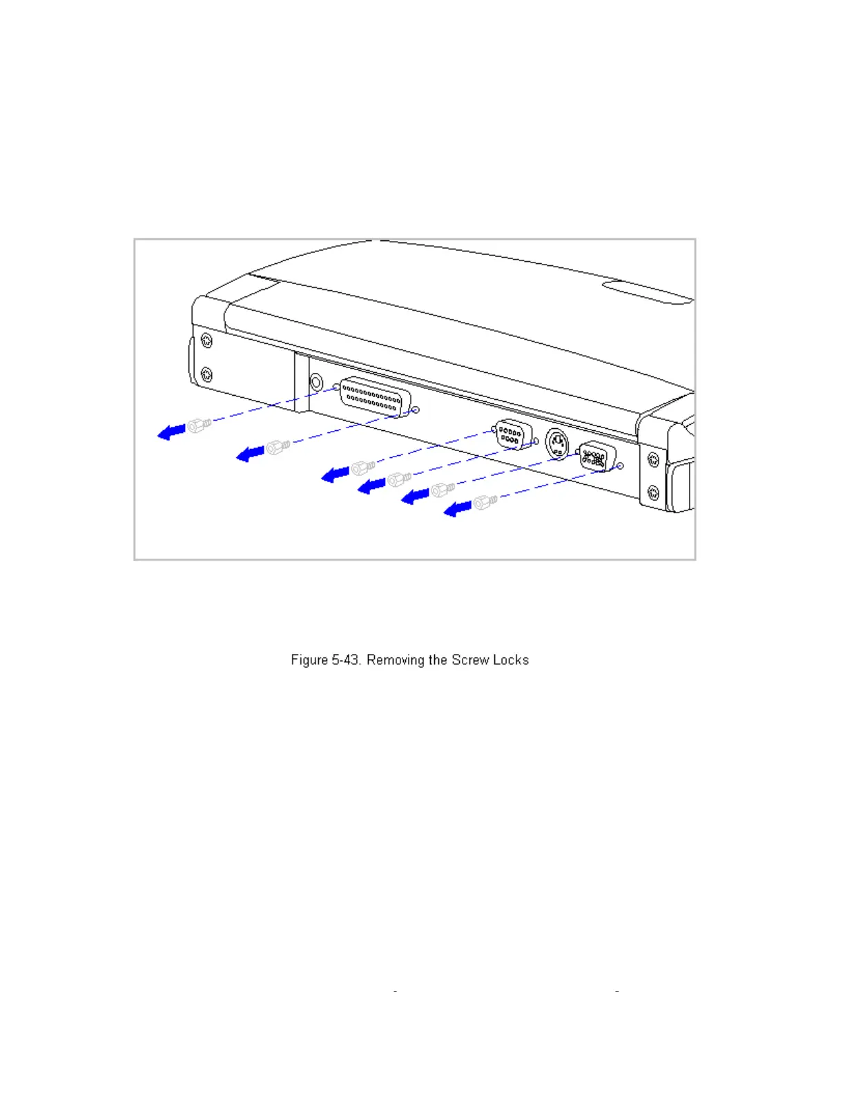
3. On the rear of the computer, use a 3/16 hex socket wrench to remove the
six screw locks (Figure 5-43).
>>>>>>>>>>>>>>>>>>>>>>>>>>>>>>>>> CAUTION <<<<<<<<<<<<<<<<<<<<<<<<<<<<<<<<<
The computer becomes top-heavy when the keyboard assembly is removed and
the display is opened. To prevent damage to the display and the computer,
ensure that the display assembly is opened at a 90-degree angle.
>>>>>>>>>>>>>>>>>>>>>>>>>>>>>>>>>>>>><<<<<<<<<<<<<<<<<<<<<<<<<<<<<<<<<<<<<<
4. Remove the keyboard assembly (Section 5.7).
5. Remove the hard drive (Section 5.9).
6. Remove the integrated trackball assembly (Section 5.11).
7. Remove the diskette drive (Section 5.12).
>>>>>>>>>>>>>>>>>>>>>>>>>>>>>>>>> CAUTION <<<<<<<<<<<<<<<<<<<<<<<<<<<<<<<<<
The ZIF connector and its attached cable can be damaged easily. Handle only
the connector slide when disconnectin
the ZIF connector. Never
ull or
 Loading...