4. To replace the lock provision plate, reverse the previous steps.
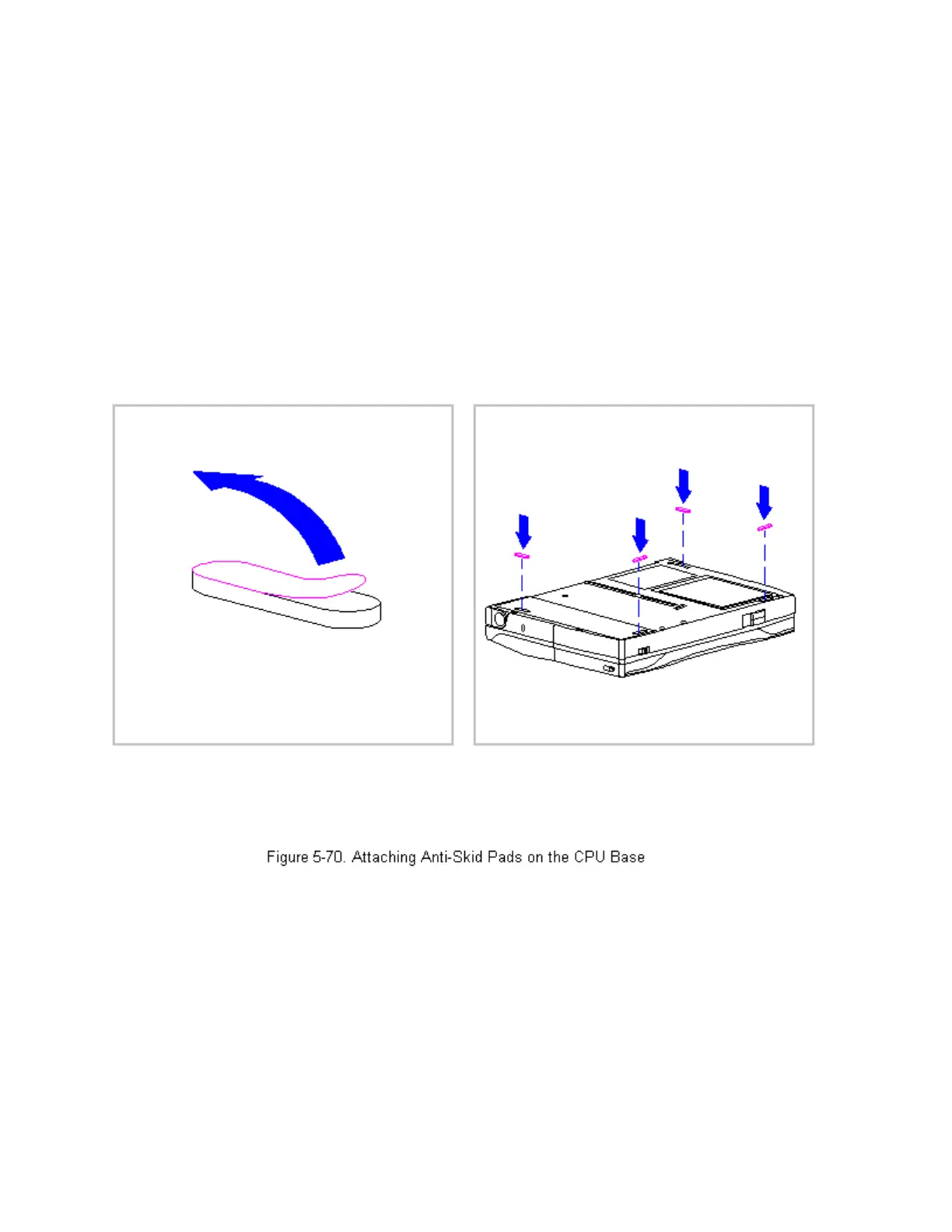
Attaching the Anti-Skid Pads
If replacing the CPU base, two anti-skid pads for the battery tray and the
two for the CPU base must be attached to the bottom of the base. To attach
the anti-skid pads, follow these steps:
1. Peel off the top layer of one of the anti-skid pads to expose the
adhesive.
2. With the adhesive side down, place the anti-skid pad into the raised
oval outline on the CPU base and the battery tray (Figure 5-70).
Display Assembly Components
This section contains removal and replacement procedures for the following
display assembly components:
 Loading...