Technical Reference Guide
Compaq Deskpro EP Series of Personal Computers
First Edition–- April1998
2-5
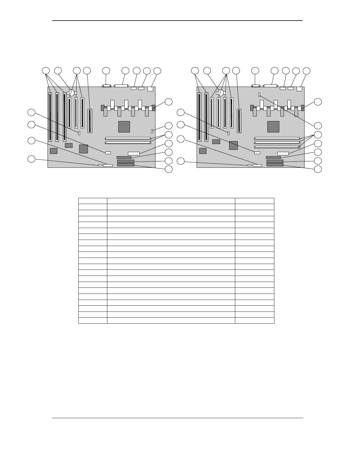
2.3.3 SYSTEM BOARD LAYOUT
Item Function Notes
1 ISA expansion connectors [1]
2 CMOS Battery
3 PCI expansion connectors [2]
4 AGP connector (J40)
5 Serial connectors (J24): top, COM2; bottom, COM1
6 Parallel interface connector (J9)
7 Mouse connector (J8)
8 Keyboard connector (J7)
9 Universal serial ports (J6): top, port B; bottom, port A
10 Microprocessor (in slot 1 connector)
11 Chassis fan connector (P8)
12 DIMM sockets (J1-J3, top to bottom) [3]
13 Power supply connector (P1)
14 Diskette drive connector (P10)
15 IDE hard drive connector (secondary) (P21)
16 IDE hard drive connector (primary) (P20)
17 CMOS/password clear jumper (E50)
18 Power LED/speaker/reset connector P5
19 Frequency select DIP switch (SW1)
20 Wake-on-LAN header P9
NOTES:
[1] On p/n 008312, J10-J12 left-to-right, J12 shares slot with PCI connector.
On p/n 009635, J11-J10 left-to-right, J10 shares slot with PCI connector.
[2] On p/n 008312, J22-J20 left-to-right, J22 shares slot with ISA connector.
On p/n 009635, J23-J20 left-to-right, J23 shares slot with ISA connector.
[3] Only two DIMM slots (J1, J2) on p/n 008312.
Figure 2–5.
System Board Layout, Component Side
100-MHz Slot 1 (3-DIMM) System Board
(ATX-type, P/N 009635-xxx)
5
6
3
17
10
19
18
7
20
1 2
11
12
16
13
14
15
4
8 9
66-MHz Slot 1 (2-DIMM) System Board
(ATX-type, P/N 008312-xxx)
5
6
3
17
10
19
18
7
20
1 2
11
12
16
13
14
15
4
8 9

 Loading...


