PM1395
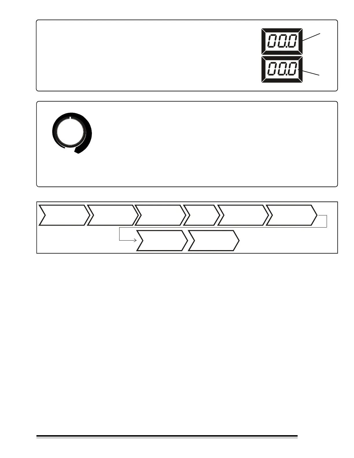
FIGURE 4-10. Voltmeter and Ammeter
1
2
V
I
FIGURE 4-11. REMOTE VOLTAGE ADJUSTMENT
REM OTE VOLTAGE
ADJUSTMENT
8
REMOTE VOLTAGE ADJUSTMENT
Use this control to set the arc voltage.
1- DIGITAL VOLTMETER.
It shows the output terminals voltage (in Volts) of the machine, but not
necessarily the arc voltage, due to the resistance of the weld cables, loose
connections, etc.
2- DIGITAL AMMETER.
It shows the weld current value in Amperes.
Install & Connect
Wire Feeder
Install & Prepare
Gun And Power
Source
Wear Safety
Equipment
Set All
Controls
Turn On
Shielding Gas
(If Applicable)
Begin
Welding
FIGURE 4-11 MIG Welding Procedure (GMAW) & Flux Cored Arc Welding (FCAW)
Turn On
Wire Feeder &
Power Source
Readjust
Controls If it is
Necessary
 Loading...