PM1395
4
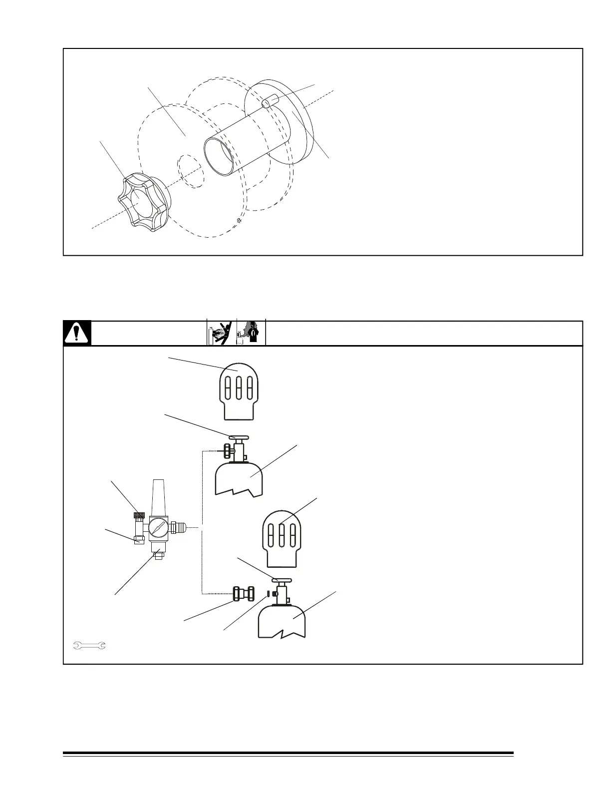
3-6. SPOOL WIRE INSTALLATION.
FIGURE 3-3 Spool Wire Installation.
For 8" and 12" (standard) wire spools
turn unit off and disconnect it.
1.- Hub spool.
2.- Pin of Hub spool.
3.- Wire spool / Reel.
4.- Hud spool cap.
Turn the hub spool cap clockwise
and remove it. Install the wire spool, be
sure the hub spool´s pin enters one of the
holes of the wire spool. Reinstall the hub
spool cap.
1
23
4
WARNING
3-7 GAS CONNECTIONS
FIGURE 3-4 Gas Connections
Cylinders' supports, chains or any stationary
support, should not damage or break the gas valve.
1.- VALVES COVER.
2.- CYLINDER VALVE: Remove cover and open
the valve slowly. Gas flow will remove dust and dirt
away the valve. Close the valve.
3.- CYLINDER.
4.- FLOW CONTROL REGULATOR.
5.- GAS CONNECTION.
6.- FLOW ADJUSTABLE KNOB: Normal flow is
20 cfh (cubic feet per hour).
7.- CO
2
ADAPTER.
8.- PACKING: Install adapter and the packing between
regulator and gas cylinder.
CYLINDERS can explode if damaged. FUMES AND GASES can be
hazardous to your health.
5/8"(15.9mm)
1 1/8"(28.6mm)
Tools needed:
1
1
3
2
4
5
6
7
8
3
2
ó
Gas
Argon
Gas CO
2