PM1395
2
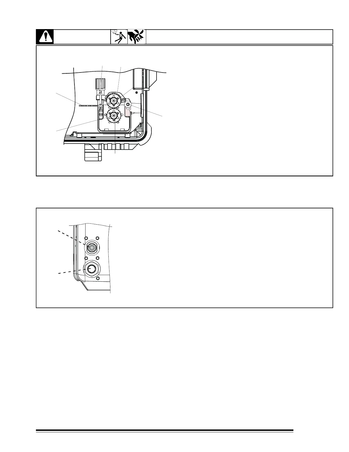
FIGURE 3-3 Gear Motor
3-2 WIRE FEEDER COMPONENTS
WARNING
ELECTRIC SHOCK can kill; ARCING can damage unit. MOVING PARTS can
cause injury.
When changing wire size, check drive rolls
and wire guide size. Before checking wire feeder
mechanism, ensure power source is disconnected
and main switch is in OFF-position.
1.- PRESSURE ADJUSTMENT KNOB
2.- INLET WIRE GUIDE
3.- DRIVE ROOL SECURITY SCREW
4.- PRESSURE GEAR ASSEMBLY
5.- DRIVE ROLL
6.- ARM SECURITY
7.- SECURITY KNOB SCREW
2
3
3-3 WIRE FEEDER CONNECTIONS
FIGURE 3-4 Wire Feeder, Rear View
1.- GAS CONNECTION. Connect to shielding gas.
2.- WELD CABLE CONNECTOR. Connect this terminal to power
source output terminal according to polarity to use.
a) STRAIGHT POLARITY: Connect this terminal to negative output
terminal on power source.
b) REVERSE POLARITY: Connect this terminal to positive output
terminal on power source.
1
2