- 33 -
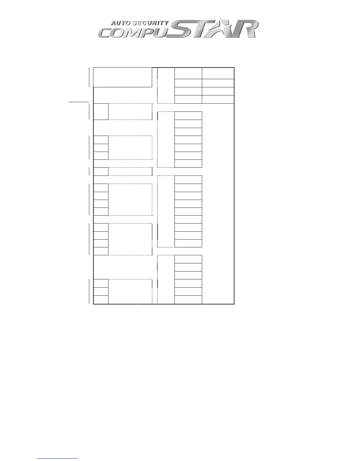
CM4200 Wiring Diagram
Cut = Auto 1 Red 2 Gr/Wht 1: ( + ) 12v Constant
2: ( + ) Parking
Light
Uncut = Manual
Jumper
3 Red/Wht 4 White 3: ( + ) 12v Constant 4: ( + ) Accessory
5 Blue 6 Yellow 5: ( + ) Output, *JM1 6: ( + ) Starter
OFF / ON
CN1
7 Gr/Red 8 Black 7: ( + ) Ignition 8: ( - ) Ground
Altenator / Tach DIP 1
15 (25) / 25 (45) DIP 2
DIP
1 Gr/Wht ( - ) Parking Lt. Output 250 mA
Gas (Diesel) 2 Red/Blk ( - ) Starter Output 250 mA
3 Violet ( - ) Output to Sterter Kill 250 mA
3 2nd Starter 4 Black ( - ) Status Out (GWR) 250 mA
2 2nd Acc 5 Orange ( - ) Rearm Output 250 mA
JM1
1 2nd Ign
CN8
6 Orange/Wh ( - ) Disarm Output
CN2
7 White ( - ) Horn Output
Tach Switch SW CN12
1 Lt. Blue ( - ) E-Brake Input
TX
4 White 2 Gray/Bk ( - ) Hood Input
RX 3 Blue 3 Lt. Blue/Wh ( + ) Brake Input
( - ) 2 Black 4 Violet/Blk ( - ) Trunk Input
( + ) 1 Red
CN7
5 Red/Wht ( - ) Door Input
6 Red ( + ) Door Input
4 ( - ) 7 Brown/Blk ( - ) Glow Plug Input
3 ( + ) 8 Brown/Wht ( + ) Glow Plug Input
2 Tx
CN3
9 Yellow/Blk Tach / Altenator Input
Antenna
1 Rx
CN11
1 None
2 Violet/Wht ( - ) Trunk Release Output 250 mA
3 Orange/Blk ( - ) 2nd Unlock Output 250 mA
3 ( - ) 4 Blue ( - ) Unlock Output 250 mA
2 Temp 5 Blue/Blk ( - ) Lock Output 250 mA
Temp Sensor
1 ( + )
CN5
CN4
6 None
* Output of Pin 5 of CN1 is determined by the placement of Jumper JM1.