CONCEPT2.COM
Page 3
012611
photo A
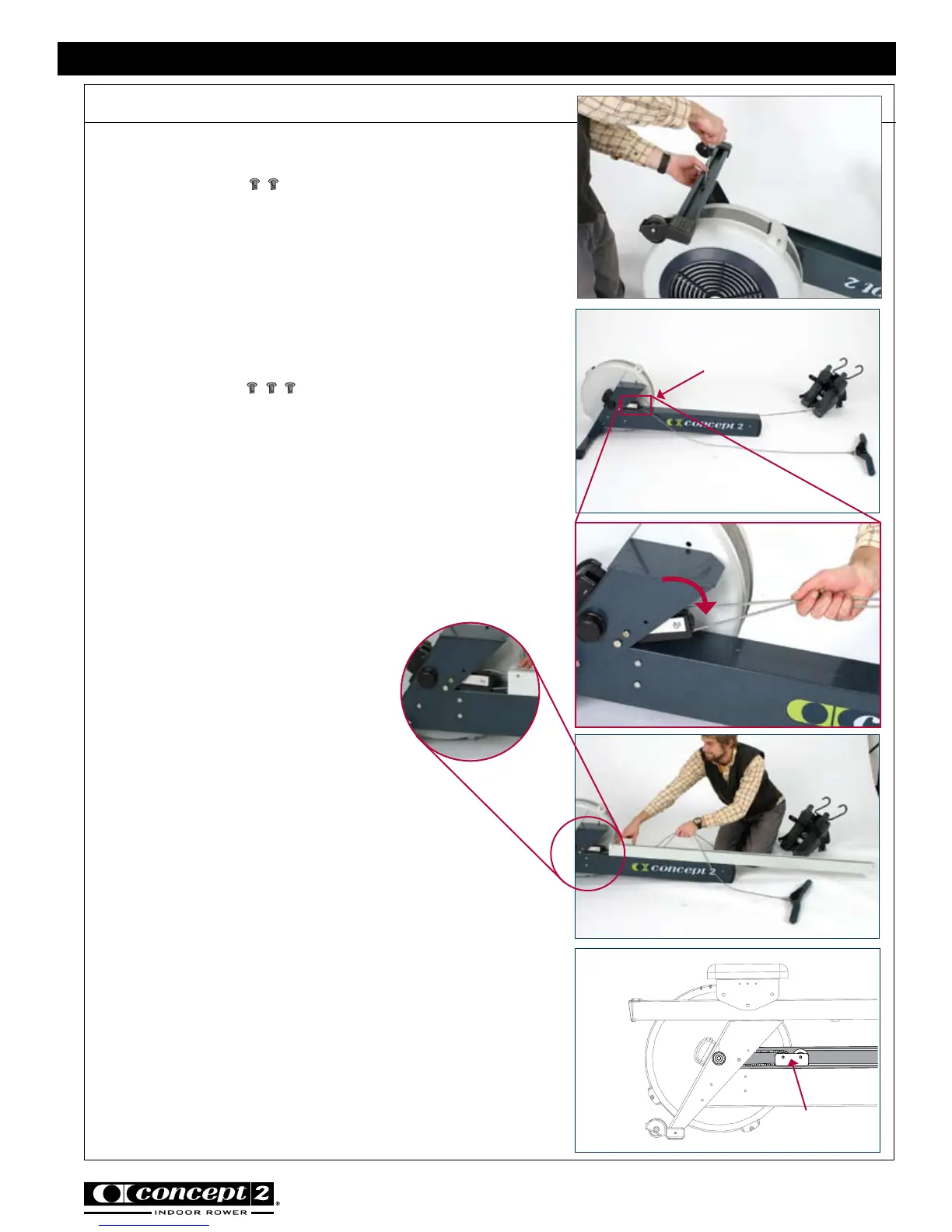
Step 2: Attach Rear Foot to Flywheel Box Assembly
photo B
Assembly Instructions
photo D
photo E
CONCEPT2 DYNAMIC INDOOR ROWER
(2) 3/8” (.95 cm)
PN 2239
Be sure that caster wheels point back, as shown in
the photo of the assembled Dynamic Indoor Rower
on page 8. Install the two screws and tighten
snugly. See photo A.
Step 3: Install Shuttle Channel
(3) 3/8” (.95 cm)
PN 2239
Position the foot carriage and handle away from the
flywheel and on either side of the flywheel return
assembly with about equal lengths of the drive cord
leading to each part. See photo B.
Note: The drive cord is a single cord that is attached
to the handle on one end and the foot carriage on
the other end.
Important: Pull shuttle down
by pulling on drive cord so that
the shuttle lies flat on the return
mechanism box. The drive cord
should be routed around the
pulley as shown. See photo C.
Position the shuttle channel with the slot facing up,
and the flange to the flywheel side. The end with
four holes in it should be away from the flywheel.
Place the outstretched drive cord through the slot
into the shuttle channel so that the foot carriage and
the handle are on either side of the shuttle channel
as shown. See photo D.
Slide the shuttle channel into the rear leg with the
shuttle positioned inside the shuttle channel. See
illustration E. Be sure the drive cord going to the
handle and foot carriage are not twisted around
each other.
Shuttle
photo C
Shuttle