CONCEPT2.COM
Page 4
012611
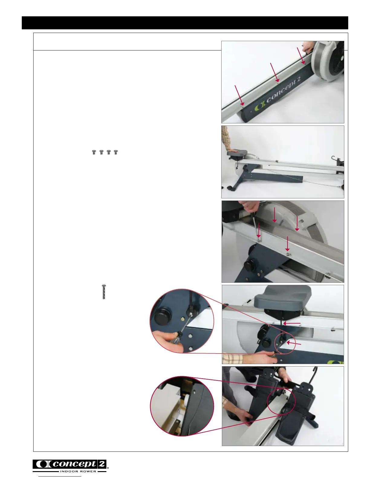
Assembly continued
Start all three 3/8” screws through the flange of the
shuttle channel into the corresponding threaded holes
in the return mechanism box. Do not fully tighten the
screws until all three screws are in place. See photo F.
Step 4: Attach Rail Assembly to Flywheel Assembly
Note: It will be helpful to have a second person
assist with this step.
(4) 3/8” (.95 cm)
PN 2239
Place the rail assembly as shown in photo G. Lift the
front end of the rail assembly up so that the bottom
lies flat against the top of the rear leg.
Start all four screws into the threaded holes. Do not
fully tighten the screws until all four screws are in
place. See photo H.
Step 5: Attach Seat Bungee
(1) 1 3/8” (3.49 cm)
PN 2228
Insert the screw through the round
seat bungee anchor and into the rear
leg. See photo I.
Hint: You will need to put tension on
the seat bungee to align the screw
with the threaded hole.
Step 6:
Slide Foot Carriage onto Rail Assembly
Slide the foot carriage onto rail
assembly as shown in photo J, making
sure the drive cord attachment to the
foot carriage extends through the slot
and into the shuttle channel.
photo F
photo H
photo J
photo G
CONCEPT2 DYNAMIC INDOOR ROWER
photo I
Seat Bungee
Seat Bungee
Anchor