CONCEPT2.COM
Page 5
012611
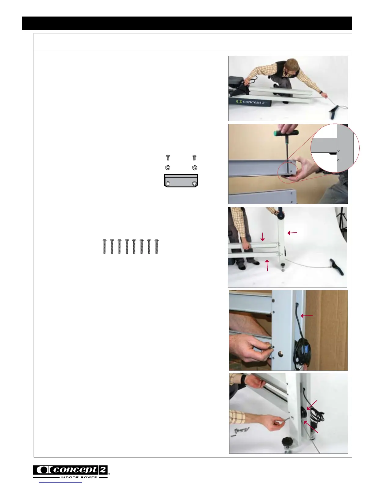
Pull the handle all the way out (away from the
flywheel) so that the drive cord is stretched out
straight in the shuttle channel. This action will cause
the foot carriage to move toward the flywheel.
See photo K. Again, be sure the drive cord going to
the handle and foot stretcher are not twisted around
each other.
Hint: Look into the open end of the shuttle channel
to ensure the drive cord is routed properly. The drive
cord attached to the handle should lay on the “floor”
of the shuttle channel.
Step 7: Install Rail Assembly End Stop
(2) 1/2” (1.27 cm) PN 2227
(1) x Rail Assembly end stop w/2 nuts
Install the rail assembly end stop on the underside
of the rail assembly. Be sure nuts are oriented down
toward the floor. See photo L.
Step 8: Attach Front Leg/Monitor Arm Assembly
(8) 1 3/8” (3.49 cm)
PN 2228
Note: You may need a second person to assist you
with aligning the holes.
Position the front leg/monitor arm assembly at end of
the shuttle channel and rail assembly. Lift the shuttle
channel and rail assembly up with one hand and slide
them between the two front legs taking care that the
handle is extended fully and the drive cord is routed
through the underside of the pulley. Take care not
to pinch the drive cord between the pulley guides
and the end of the shuttle channel. See photo M.
Hint: Insert one 20-penny nail through the top
fastener hole into the rail assembly and one 20-penny
nail through the top fastener hole into the shuttle
channel to temporarily align all fastener holes. Note
that these nails will be replaced with the screws. See
photo N.
Once you have the parts aligned, insert screws but
do not fully tighten until all eight screws are in place.
Note that you may need to jostle the rail assembly
and shuttle channel to get the screws started.
See photo O.
photo L
photo O
photo N
Assembly continued
CONCEPT2 DYNAMIC INDOOR ROWER
Pulley
Pulley
Guides
Front Leg/
Monitor Arm
Assembly
Rail Assembly
Rail Assembly
Shuttle Channel
1
2
photo M
Shuttle
Channel
Front Leg/
Monitor Arm
Assembly
Rail
Assembly
photo K